


8
Assembly (cont.)
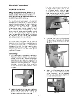
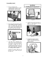
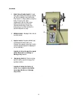
5. Mount the headstock side
comparator/guard bracket on top of the
support as shown in Figure 10. Use
the supplied 6mm Allen head bolts.
Figure 10
6. Mount the second comparator bracket
to the tailstock as shown in Figure 11
using the supplied 6mm Allen head
bolts. As well, the comparator pin A has
been installed. Notice the flat part of the
pin faces the bolt of the lock handle.
Figure 11
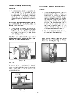
7. Your Oliver lathe is equipped with a
safety shield. Install the mounting post
of the shield, in the direction shown by
the arrow in Figure 12, into the
comparator/guard bracket and lock into
place with the lock handle. Loosen the
lock handle to adjust the guard position
as necessary and then re-tighten.
If desired, the safety shield can be
removed in order to install the second
comparator pin.
CAUTION!
Eye protection must always be worn whether
the safety shield is installed or not!
Figure 12
8. Install the motor tension rod as shown in
Figure 13. Once threaded in, lock into
place with the jam nut A.
Figure 13
9. The inboard tool rest can now be
installed in its holder as shown in
Figure 14. Once set in place lock it
using the handle A.
Figure 14
Содержание 2018
Страница 2: ...Date Maintenance Notes...
Страница 19: ...HEADSTOCK 95...
Страница 22: ...LATHE BED...
Страница 24: ...TOOL REST TAIL STOCK...
Страница 26: ...MOTOR INVERTER E...
Страница 28: ...Guard Comparator...


