OLIMEX© 2015
STM32-P405 user's manual
Page 27 of 31
5VAC
6VDC
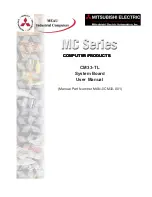
Notes:
=====
1. When STM32F405RET6(LQFP64) is mounted, C22 and C24 must be populated!
2. When STM32F103RBT6(LQFP64) is mounted, C22 and C24 must be short circuit(for example with 0 Ohm resistor)
3. U1's symbol refers to STM32F103RBT6(LQFP64).
For the STM32F405RET6(LQFP64), please see the corresponding datasheet!
VCAP_1
VCAP_2
STM32F405RET6(LQFP64)
STM32-P405, board revision D
Designed and assembled by Olimex LTD, Bulgaria
https://www.OLIMEX.com
+5V_USB
3.3V
1
2
3.3V_MCU_E
0
2
1
3
B1_H/B1_L
1
2
BAT_3V
CON2PV2-2.54MM
1
2
BAT_E
0
C1
100nF
C2
C3
C4
C5
100nF
C6
100nF
C7
100nF
C8
10uF/10V
C9
100nF
C10
100nF
C11
10uF/10V
C12
27pF
C13
27pF
C14
10pF
C15
10pF
C16
47pF(NA)
C17
47pF(NA)
C18
100nF
C19
100n
C20
C21
C22
2.2uF/6.3V
C23
100nF
C24
2.2uF/6.3V
C25
100n
C26
100n
C27
100n
C28
100nF
C29
C30
C37
100nF
C41
100nF
1
2
3
CAN
CON33.5MM
1
3
CNTRL/HS
1
2
CP_E
0
1
2
CTS_E
D1
1N5819S
D2
1N5819S
G1
DB104(SMD)
GND
GNDA
1
2
3
4
5
6
7
8
9
10
11
12
13
14
15
16
17
18
19
20
JTAG
L1
ferrite bead
L2
470nH
1
2
LED_E
0
VIN
PA1
PA8
PB0
PB1
PB2
PB5
PB8
PB9
PB10
PB11
PB12
PB13
PB14
PB15
PC0
PC1
PC2
PC3
PC4
PC5
PC6
PC7
PC8
PC9
PC10
PC12
PC13
PD2
PWR
PWR_JACK
Q1
8MHz
GND
Q232768
Q3
BC817
Q4
BC817
R-T
R1
10k
R2
10k
R3
10k
R4
10K
R5
10k
R6
10k
R7
2k
R8
10k
R9
390/1%
R10
240/1%
R11
10k
R12
1M
R13
10k
0R
R14
0R(Board_Mounted)
R15
100K
R16
330
R17
100K
R18
10K
R19
15K
R20
10k
R21
22
R22
22
R23
NC
R24
22K
R27
120
R28
10K
R33
22K
R34
1K
R35
2k
R36
10k
R37
10k
R38
33K
R39
2K
R42
2K
R43
33K
R44
10K
R45
10K
R49 10K
R50
33k
R51
1.5K
R52
47k
R53
1K
R54
100K
R59
10K
RESET
1
2
3
4
5
6
7
8
9
RS232_2
RST
1
2
RTS_E
SD/MMC
SD_CARDBOT
CD/DAT3/CS
1
CLK/SCLK
5
CMD/DI
2
CP1
13
CP2
15
DAT0/DO
7
DAT1/RES
8
DAT2/RES
9
VDD
4
VSS1
3
VSS2
6
WP1
10
WP2
14
STAT
RED
BOOT0
60
NRST
7
PA0-WKUP/USART2_CTS/ADC0/TIM2_CH1_ETR
14
PA1/USART2_RTS/ADC1/TIM2_CH2
15
PA2/USART2_TX/ADC2/TIM2_CH3
16
PA3/USART2_RX/ADC3/TIM2_CH4
17
PA4/SPI1_NSS/USART2_CK/ADC4
20
PA5/SPI1_SCK/ADC5
21
PA6/SPI1_MISO/ADC6/TIM3_CH1/TIM1_BKIN
22
PA7/SPI1_MOSI/ADC7/TIM3_CH2/TIM1_CH1N
23
PA8/USART1_CK/TIM1_CH1/MCO
41
PA9/USART1_TX/TIM1_CH2
42
PA10/USART1_RX/TIM1_CH3
43
PA11/USART1_CTS/CANRX/USBDM/TIM1_CH4
44
PA12/USART1_RTS/CANTX/USBDP/TIM1_ETR
45
PA13/JTMS/SWDIO
46
PA14/JTCK/SWCLK
49
PA15/JTDI/TIM2_CH1_ETR/SPI1_NSS
50
PB0/ADC8/TIM3_CH3/TIM1_CH2N
26
PB1/ADC9/TIM3_CH4/TIM1_CH3N
27
PB2/BOOT1
28
PB3/JTDO/TIM2_CH2/TRACESWO/SPI1_SCK
55
PB4/JTRST/TIM3_CH1/SPI1_MISO
56
PB5/I2C1_SMBAI/TIM3_CH2/SPI1_MOSI
57
PB6/I2C1_SCL/TIM4_CH1/USART1_TX
58
PB7/I2C1_SDA/TIM4_CH2/USART1_RX
59
PB8/TIM4_CH3/I2C1_SCL/CANRX
61
PB9/TIM4_CH4/I2C1_SDA/CANTX
62
PB10/I2C2_SCL/USART3_TX/TIM2_CH3
29
PB11/I2C2_SDA/USART3_RX/TIM2_CH4
30
PB12/SPI2_NSS/I2C2_SMBAL/USART3_CK/TIM1_BKIN
33
PB13/SPI2_SCK/USART3_CTS/TIM1_CH1N
34
PB14/SPI2_MISO/USART3_RTS/TIM1_CH2N
35
PB15/SPI2_MOSI/TIM1_CH3N
36
PC0/ADC10
8
PC1/ADC11
9
PC2/ADC12
10
PC3/ADC13
11
PC4/ADC14
24
PC5/ADC15
25
PC6/TIM3_CH1
37
PC7/TIM3_CH2
38
PC8/TIM3_CH3
39
PC9/TIM3_CH4
40
PC10/USART3_TX
51
PC11/USART3_RX
52
PC12/USART3_CK
53
PC13/ANTI_TAMP
2
PC14/OSC32_IN
3
PC15/OSC32_OUT
4
PD0/OSC_IN
5
PD1/OSC_OUT
6
PD2/TIM3_ETR
54
VBAT
1
VDD
32
VDD
48
VDD
64
VDD
19
VDDA
13
VSS
31
VSS
47
VSS
63
VSS
18
VSSA
12
U1
STM32F103RBT6(LQFP64)
U2
NA
GND
VCC
RESET
1
2
U3
SN65HVD230
CANH
7
CANL
6
RS
8
RXD
4
TXD
1
VDD
3
VREF
5
VSS
2
1
2
3
4
5
6
U4
USBLC6-2P6(NA)
C1+
1
C1-
3
C2+
4
C2-
5
R1IN 13
R1OUT
12
R2IN 8
R2OUT
9
T1IN
11
T1OUT14
T2IN
10
T2OUT7
V+
2
V-
6
U5
ST3232
GND
VCC
15
16
U5PWR
UEXT-1
UEXT-2
UEXT-3
UEXT-4
UEXT-5
UEXT-6
UEXT-7
UEXT-8
UEXT-9
UEXT-10
1
2
3
4
USB
1
2
USB_P
3.3V
3.3V
3.3V
VDDA
3.3V
3.3V
3.3V
3.3V
3.3V
3.3V
3.3V
3.3V
3.3V
3.3V
3.3V
3.3V
3.3V
3.3V
3.3V
3.3V
3.3V
3.3V
3.3V
3.3V
VDDA
VIN
ADJ/GND
IN
OUT
VR1(3.3V)
LM1117
WAKE-UP
1
2
WP_E
0
TRST,TDI,TMS,TCK,TDO,RST
+5V_USB
ADC15
BOOT0
CAN_RX
CAN_RX
CAN_TX
CAN_TX
CNTRL
CNTRL
CP
CP
DISC
DISC
I2C1_SCL
I2C1_SCL
I2C1_SDA
I2C1_SDA
LED
LED
RST
RST
RST
RST
SPI1_MISO
SPI1_MISO
SPI1_MOSI
SPI1_MOSI
SPI1_NSS
SPI1_NSS
SPI1_SCK
SPI1_SCK
SPI2_MISO
SPI2_MISO
SPI2_MOSI
SPI2_MOSI
SPI2_NSS
SPI2_NSS
SPI2_SCK
SPI2_SCK
TCK
TCK
TDI
TDI
TDO
TDO
TMS
TMS
TRST
TRST
UART2_RTS
UART2_RTS
USART1_RX
USART1_RX
USART1_TX
USART1_TX
USART2_RX
USART2_RX
USART2_TX
USART2_TX
USBDM
USBDM
USBDP
USBDP
USB_P
USB_P
VCC
WAKE-UP
WAKE-UP
WAKE-UP
WP
WP