CHAPTER 3 MAINTENANCE PROCEDURES
Navigator Series Service Manual
23
Ohaus Corporation www.ohaus.com
3.4 REPLACING THE PRINTED CIRCUIT BOARD AND DISPLAY
1. Open the scale
– see Section 3.2.
2. Pick the PCB off its mounting pins and position the PCB upside-down so that the load cell wire
connection is easy to access.
3. Disconnect the Load Cell cable from the PCB. The load cell connection is a five-wire cable
that is soldered directly to the PCB. Before disconnecting the cable record the wire colors and
their location on the PCB. (Hint: A digital picture is an easy and reliable record.) Disconnect
the cable connecting the PCB to the Load Cell by un-soldering the 5 wires from the PCB.
Take care not to over heat the PCB which will damage the thin PCB conductors.
4. Unsolder the AC Cable wires from the PCB.
5. Follow these steps in reverse order to install the new PCB.
6. Configure the Scale. (See Appendix C.)
Note:
The PCB and the LCD Display are supplied as a single unit. However, if only the LCD
Display needs replacement, it can be separated from the PCB by unsoldering the fine lead-wires
connecting it to the PCB. When installing the new LCD Display, carefully feed the lead-wires
through their holes, check that the new assembly is seated properly on the PCB and then solder the
lead-wires.
3.5 REPLACING THE FUNCTION LABEL
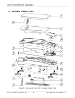
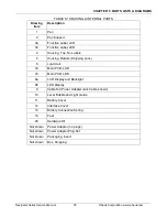
The Function Label may need to be replaced. (See Chapter 5 for parts information.) Use a broad
blade, such as a wide X-Acto
™ knife, to remove the label. Clean the glue residue from the Housing
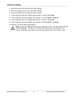
surface. Then carefully place the new label where the old one was. (See Figure 3-8.)
Figure 3-5. Function Label Removal
3.6 DOWN-STOP ADJUSTMENT
The purpose of the down-stops is to protect the load cell from physical damage. The down-stops are
created by contacting bosses in the Base and adjustment screws or bosses in the Sub-Pan. The NV
models have 3 down-stops, left, right and center near the load cell attachment to the Sub-Pan. The
NVL and NVT models have 5 down-stops, left-front, left-rear, right-front, right-rear and center near
the load cell attachment to the Sub-Pan.
NV models with capacity greater than 2kg and NVL / NVT models with a capacity greater than 10kg
do not have adjustable down-stops. The down-stop bosses on the Sub-pan are designed to be at
the correct distance to protect these load cells. The smaller capacity load cells require the down-
stop clearance to be decreased for proper load cell protection. Adjustment screws are placed in the
Sub-pan down-stop bosses to reduce the clearance, see figure 3-6.
Function Label
Содержание Navigator NV1101
Страница 1: ...SERVICE MANUAL Navigator Series Scales ...
Страница 2: ......
Страница 6: ......
Страница 56: ......
Страница 57: ......


