CHAPTER 3 MAINTENANCE AND REPAIR PROCEDURES
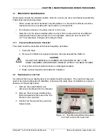
3.2 Replacing the Load Cell
4. Remove the bottom Load Cell
Mounting Bolts, washers and spacer.
The Load Cell assembly can now be
removed from the Lower Frame.
5. Install the new Load Cell following
steps 1 through 4 in reverse order.
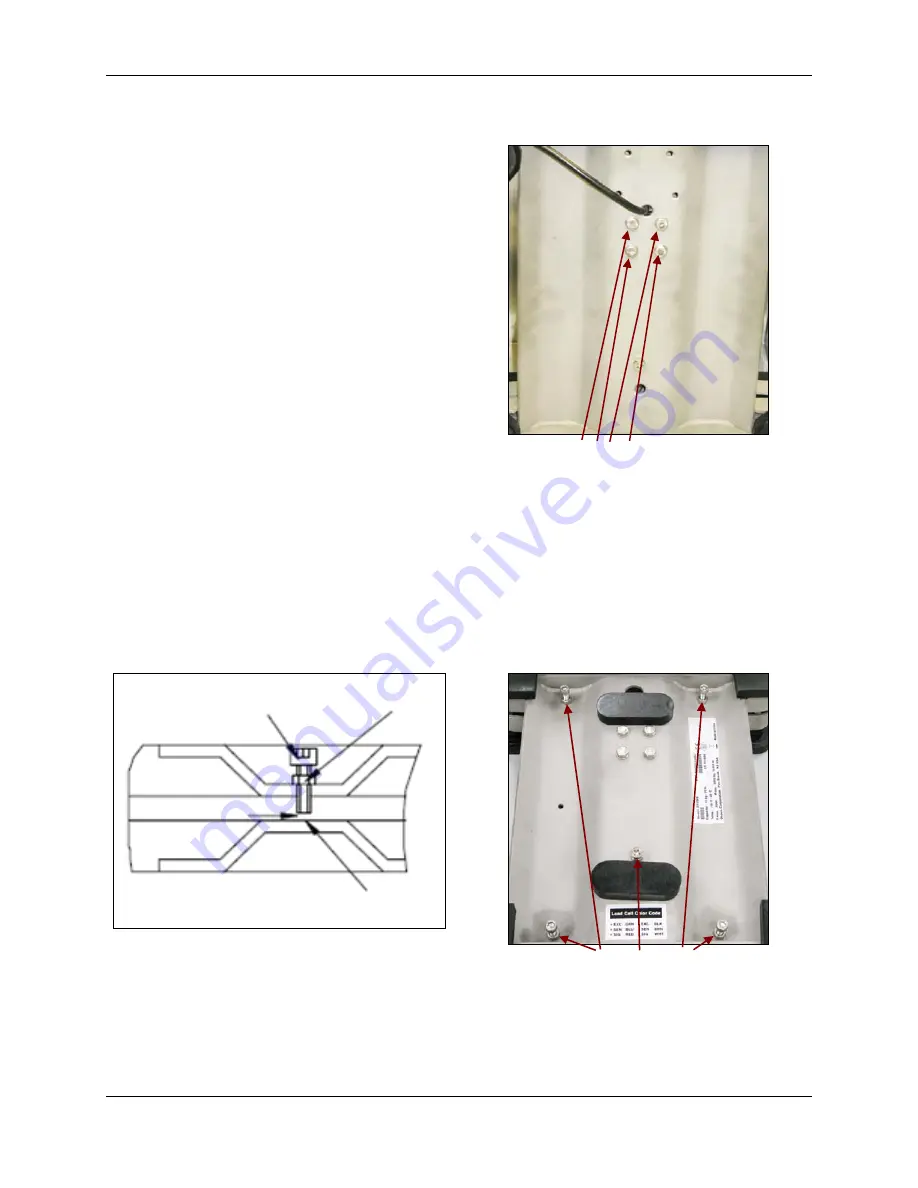
Figure 3-2. Four Mounting Bolts that secure
the Bottom Frame to the Load Cell.
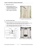
3.3 Overload Stop Adjustments
The Overload Stop gaps must be checked and reset if the Load Cell is replaced.
1. Remove the Platform and loosen the Jam Nuts, first on the four Overload Stops on the
top side of the Frame, then on the bottom. (See Figures 3-3, 3-4 and 3-5.)
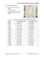
2. Use the appropriate size feeler gauge in the Gap (see Table 3-1), and turn the set
screws until a slight drag is felt on the feeler gauge.
Figure 3-3. Overload Gap Setting.
Figure 3-4. Location of top Overload Stops.
Jam Nut
Overload Stop
Set Screw
Gap
Ohaus Corporation www.ohaus.com
3-2
Defender™ H-Q-W Series Service Manual
Содержание Defender D15HR
Страница 2: ......
Страница 4: ......
Страница 14: ...CHAPTER 1 INTRODUCTION Ohaus Corporation www ohaus com 1 8 Defender H Q W Series Service Manual...
Страница 16: ...CHAPTER 2 DIAGNOSTIC GUIDE Ohaus Corporation www ohaus com 2 2 Defender H Q W Series Service Manual...
Страница 32: ...CHAPTER 5 PARTS LISTS DIAGRAMS Ohaus Corporation www ohaus com 5 6 Defender H Q W Series Service Manual...
Страница 34: ...APPENDIX A GLOSSARY Ohaus Corporation www ohaus com A 2 Defender H Q W Series Service Manual...
Страница 35: ......
Страница 36: ...80252596 P N 80252596 SERVICE MANUAL DEFENDER H Q W SERIES BASES...


