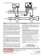

WIRING
Carefully follow the terminal diagram pictured on the con-
troller’s housing and shown above. The power and load
wiring should be 18 AWG or larger size. Be sure to observe
that the ratings for voltage and current are not exceeded. All
local and national electrical codes must be followed. Use only
the sensor type as indicated on the control and maintain cor-
rect polarity. THE RED THERMOCOUPLE LEAD ALWAYS
CONNECTS TO THE NEGATIVE (–) TERMINAL.
To reduce electrical noise, the thermocouple wire must be iso-
lated from any power or heater wiring. Shielded thermocou-
ple wire may be necessary in high noise environments or
when lead lengths exceed 10 feet. Thermocouples are tip
sensitive and must be in good mechanical contact with the
load.
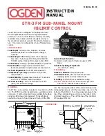
OPERATION
The set point temperature is adjustable by turning the integral
dial. If the set point is exceeded, contacts 4 and 5 will open.
It will remain in this state until the temperature drops below
the set point and the controller is manually reset. Manual
reset can be accomplished by one of the following means: a)
Press the “reset button”. b) A momentary switch closure
between terminals 8 and 9. c) Interrupt power to the control.
CAUTION
This controller must be mounted in an enclosure suitable for
protection against normally expected operation environments
and to minimize unauthorized tampering with the limit set-
tings. This control is not to be used in hazardous locations as
defined in Articles 500 and 505 of the National Electric Code.
MAINTENANCE
No specific maintenance is required. However, it is recom-
mended that all wiring be checked periodically for loose con-
nections and damaged wires. Disconnect power to the panel
before any maintenance is performed. Check wires and
tighten connections.
TROUBLE SHOOTING
RISK OF ELECTRIC SHOCK -
Dangerous and potentially
fatal voltages are present when working on this equipment.
Before installation or beginning any troubleshooting proce-
dures, the electric power to this equipment must be discon-
nected and locked out as described by OSHA Standards.
Units suspected of being faulty must be removed and
returned to Ogden for inspection and/or repair. They contain
no user serviceable components.
Experience has proven that many control problems are not
caused by a defective instrument.
Some of the common causes of failure are broken sensors,
open fuses and poor wire connections.
If these points have been checked and the control still does
not function, it is suggested that the instrument be returned
for inspection.
Use adequate packing materials to prevent damage in
shipment.
Return Control To:
OGDEN MANUFACTURING CO.
ATTN: Repair Department
64 West Seegers Road, Arlington Heights, IL 60005
(847) 593-8050 • Fax: (847) 593-8062
www.ogdenmfg.com
©Ogden Manufacturing Co. 2001 PRINTED IN U.S.A. 02/2001
OGDEN and ETR are Registered
Trademarks of
Ogden Manufacturing Co.
MARCA REGISTRADA
Specifications subject to change without notice.
1
2
3
4
5
6
7
8
9
ETR-3
Limit
150
200
350
300
°
F
NC
NO
C
Primary
Temperature
Control
NC
NO
120VAC
Optional N.O.
Remote Reset
Switch
T/C or RTD
Coil
Control
Fuse
5A
T/C
or
RTD
H
N
Heater Power
1 or 3 Phase
120V
Control
Power
Heater
Fuses
Coil
Primary
Control
Contactor
ETR-3
Limit
Contactor
Heater(s)
Optional Alarm
or Warning
Lamp
+ –
C
TYPICAL WIRING DIAGRAM