background image


IR Configuration 

The 

I.R. 

can be sent in 1 of 2 directions: 1) Receiver to Transmitter 

unit OR 2) from Transmitter to Receiver unit. 
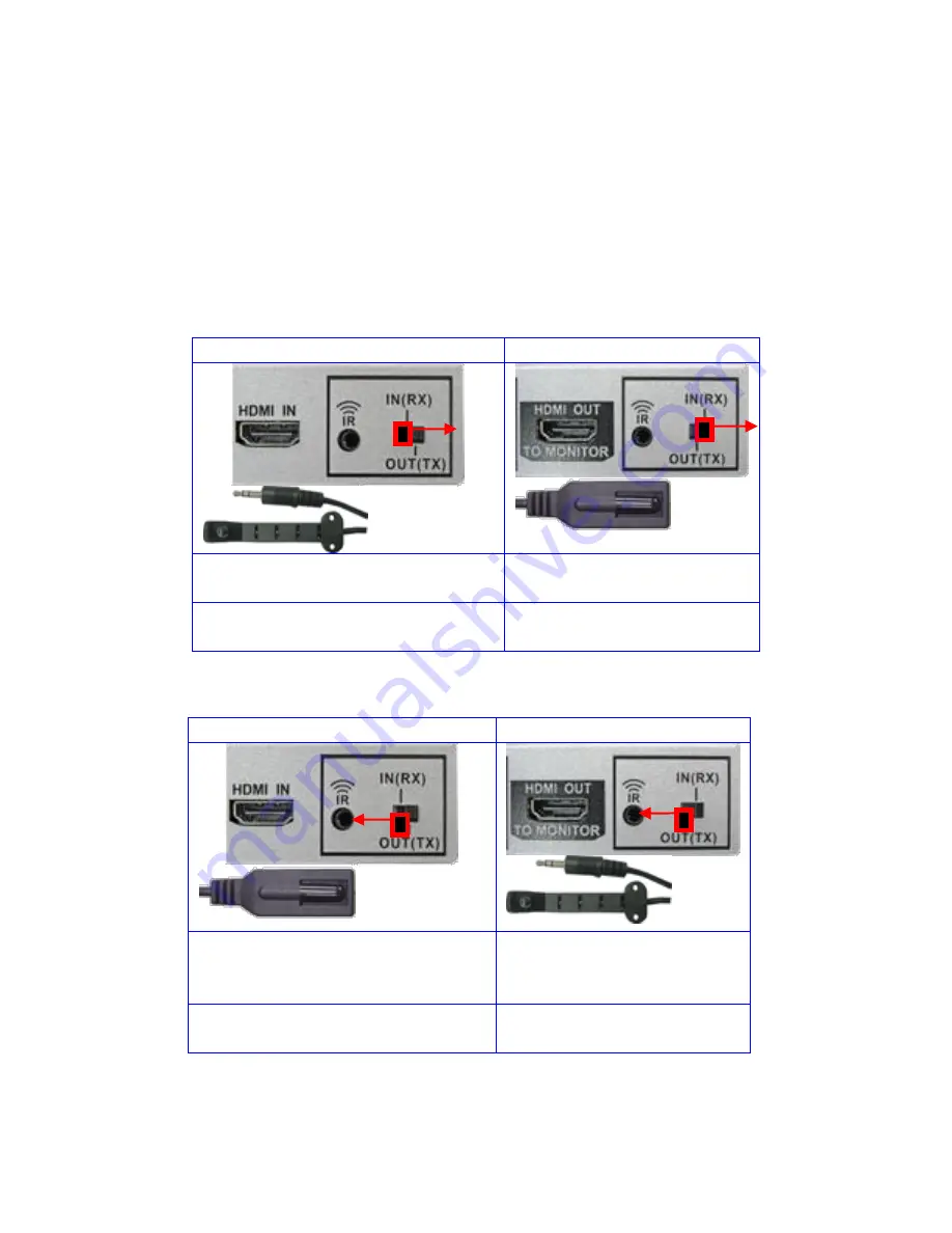
 

Configuration 1:   

Sending


IR from

 Receiver to Transmitter

 Unit 


Configuration 2:   

Sending


IR from 

Transmitter to Receiver

 Unit. 

Transmitter Unit 

Receiver Unit 


Set IR switch to the 
IN(RX)position as shown 

Set IR switch to the 
OUT(TX)position as 
shown 

Connect IR receiver cable to IR 
port. 

Connect IR transmitter 
cable to IR port. 


Transmitter Unit 

Receiver Unit 


Set IR switch to the OUT(TX) 
position as shown 

Set IR switch to the 
IN(RX)position as shown 

Connect IR transmitter cable to 
IR port. 

Connect IR receiver 
cable to IR port. 

Содержание HDOCAT-BD

Страница 1: ...1 Installation Guide ...

Страница 2: ...2 Contents Description 3 Features 4 Application Diagram 4 Installation 5 Toslink Digital Audio Configuration 6 IR Configuration 7 Mounting Tabs 8 Powering Options 9 Specifications 10 ...

Страница 3: ...er unit Perfect for sending digital audio from IP Web based HDTV back to audio receiver The direction is configured by user selectable switch CAT 6 cable is recommended for 1080P and best performance The HDMI over Ethernet Extender allows installers to use standard CAT 5 6 cables for ease of installation Ethernet cables and connectors are easily field terminated thus allowing installers to easily ...

Страница 4: ...D support 120ft 1080p over Ethernet CAT 6 cables 6 75 Gbps aggregate data rate Ethernet cables for easy field installation No custom length cables needed Active Drive and Compensation for Error Free Transmission Perfect for Projector or Digital Signage applications Send Digital Toslink from IP based HDTV back to Audio receiver Dedicated external powering for ultimate reliability Application Diagra...

Страница 5: ...r and Receiver With CAT5e 6 cable 3 IR connection configure and connect as shown in section IR Configuration see page 5 4 Toslink Digital Audio configure and connect as shown in section Toslink Digital Audio Configuration see page 6 5 Connect Power supplies 6 Connect HD source to HDMI In of Transmitter unit Connect HDTV to HDMI out of Receiver unit ...

Страница 6: ...o from Transmitter to Receiver unit Transmitter Unit Receiver Unit Set Digital Audio Optical switch to the OUT position as shown Set Digital Audio Optical switch to the IN position as shown Connect Toslink cable to Optical OUTPUT Connect Toslink cable to Optical INPUT Transmitter Unit Receiver Unit Set Digital Audio Optical switch to the IN position as shown Set Digital Audio Optical switch to the...

Страница 7: ...ransmitter to Receiver Unit Transmitter Unit Receiver Unit Set IR switch to the IN RX position as shown Set IR switch to the OUT TX position as shown Connect IR receiver cable to IR port Connect IR transmitter cable to IR port Transmitter Unit Receiver Unit Set IR switch to the OUT TX position as shown Set IR switch to the IN RX position as shown Connect IR transmitter cable to IR port Connect IR ...

Страница 8: ...8 Mounting Tabs The HDOCAT BD includes removable wall mounting tabs The wall mounting tabs can be removed if not needed wall mounting tabs installed Wall mounting tabs can be removed if not needed ...

Страница 9: ...power supply Power from power supplies included USB to 2 5mmDC plug power cable for receiver Transmitter connect power supply Receiver connect USB to 2 5mm DC plug power cable to HDTV USB port Power Receiver from USB to DC adapter cable Must have HDTV with USB2 that can supply 500mA 2 5mm DC plug power cable ...

Страница 10: ... RX unit Optical Digital Audio In Out 1 user configurable Optical Toslink direction is user configured as 1 from RX unit to TX OR 2 from TX unit to RX unit Infrared Frequency 20 KHz 60 KHz Ethernet cables required 2 Ethernet Cable CAT 6 Recommended for 1080P and best performance EIA TIA 568 B termination T568B recommended Punch down connection block panel will degrade performance and not recommend...

Отзывы: