C-Nav7050 User Guide
Revision 0
Page 12 of 27
10/30/2020
Control Micro
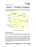
The control microprocessor is connected to both UHF modules and is capable
of sending and confirming commands to change the current channel. The
current channel number is shown on a front panel combined display / switch
unit. The processor can also perform a scan of all programmed channels and
select the one with the best signal to noise ratio. Frequency selection and
scanning are thus possible without connection to an external PC.
IALA Radio Module
The IALA radio module can be configured via a port on the back panel. It is
normally set to auto scan for the highest signal strength. The output from the
IALA receiver is passed to the fallback switch. See Appendix C - IALA Module
(Page
) for further information.
Auxiliary Input
In addition to the two UHF and one IALA sources it is also possible to use
corrections from an external system via a back panel serial port. These could be
derived from a PPP corrected receiver or be broadcast from a local RTCM base.
There is hardware present to support the future option of having the auxiliary
source be an Ethernet connection. A Lantronix X-Port module converts the
Ethernet data to serial. When supported in a future release, the choice of serial
or Ethernet will be mad by a switch on the back of the unit. At this time, the
switch should
always be in the “serial” position.
Fallback Switch
The fallback switch examines the output of the Primary Source for data and if
data is absent for a period of time the fallback switch output changes to the
Secondary correction source. The sample period can be adjusted by an internal
control. Should Primary source data be detected then the corrections outputs
will switch back to the Primary source.
Dual Outputs
The data stream selected by the fallback switch is output by two opto-isolated
RS- 232 ports. There are two RTCM104 outputs located on the rear panel of the
C-Nav7050.


