Ocean Optics USB2000 Скачать руководство пользователя страница 39


Appendix A 

USB2000 Operating Instructions 

34


Saving the New Calibration Coefficients: USB Mode 

Ocean Optics programs wavelength calibration coefficients unique to each USB2000 onto an EEPROM memory 
chip in the USB2000.  

You can overwrite old calibration coefficients on the EEPROM


if you are using the USB2000 via the USB port. If 

you are using the USB2000 via the serial port, consult the 

Saving the New Calibration Coefficients: Serial Mode


section later in this Appendix. 

To Save Wavelength Calibration Coefficients Using the USB Mode 

1.  Ensure that the USB2000 is connected to the PC and that you have closed all other applications. 

2.  Point your browser to


http://www.oceanoptics.com/technical/softwaredownloads.asp and scroll down to 

Microcode

. Click on the 

USB EEPROM Programmer

 selection. 

3.  Save the setup file to your computer.  

4. Run 

the 

Setup.exe

 file to install the software. The Welcome screen appears. 

5. Click 

the 

Next

 button. The Destination Location screen appears. 

6.  Accept the default installation location, or click the 

Browse

 button to specify a directory. Then, click the 

Next 

button. The Program Manager Group screen appears. 

7. Click 

the 

Next

 button. The Start Installation screen appears.  

8. Click 

the 

Next

 button to begin the installation. Once the installation finishes, the Installation Complete 

screen appears. 

9. Click 

the 

Finish

 button and reboot the computer when prompted. 

10.  Navigate to the 

USB EEPROM Programmer

 from the Start menu and run the software. 

11.  Click on the appropriate USB2000 device displayed in the left pane of the USB Programmer screen. 

12.  Double-click on each of the calibration coefficients displayed in the right pane of the USB Programmer 

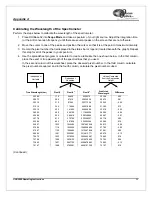
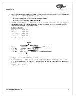
screen and enter the new values acquired in Steps 5 and 6 of the 

Calibrating the Wavelength of the 

Spectrometer

 section in this Appendix. 

13.  Repeat Step 12 for all of the new values. 

14.  Click on the 

Save All Values

 button to save the information, and then 

Exit

 the USB Programmer 

software. 

The new wavelength calibration coefficients are now loaded onto the EEPROM memory chip on the USB2000. 

Содержание USB2000

Страница 1: ...727 733 2447 Fax 727 733 3962 8 a m 8 p m Mon Thu 8 a m 6 p m Fri EST Ocean Optics B V Europe Geograaf 24 6921 EW DUIVEN The Netherlands Phone 31 0 26 3190500 Fax 31 0 26 3190505 E mail Info OceanOpt...

Страница 2: ......

Страница 3: ...consent of Ocean Optics Inc in any form of binding or cover other than that in which it is published Trademarks Microsoft Windows Windows 95 Windows 98 Windows ME Windows NT Windows 2000 Windows XP a...

Страница 4: ...ectrometer Specifications 7 System Compatibility 8 10 pin Accessory Connector Pinout 8 10 Pin Accessory Connector Pinout Diagram 9 10 Pin Accessory Connector Pin Definitions 9 10 Pin J2 Accessory Conn...

Страница 5: ...avelength of the USB2000 31 About Wavelength Calibration 31 Calibrating the Spectrometer 31 Preparing for Calibration 31 Calibrating the Wavelength of the Spectrometer 32 Saving the New Calibration Co...

Страница 6: ...sized PCs Ocean Optics OOIBase32 software application installed and configured for use with the USB2000 OOIPS2000 software if using a palm sized PC Consult the Configuring the USB2000 in OOIBase32 se...

Страница 7: ...elements USB2000 Spectrometer OOIBase32 operating software Light source Sampling optics varying depending on application requirements How Sampling Works The following list explains the function of Oce...

Страница 8: ...zed PC comes with 5 VDC power supply required when connecting to serial port Shipment Components The following information and documentation ships with the USB2000 Spectrometer Packing List The packin...

Страница 9: ...instructions for the OOIBase32 Spectrometer Operating Software at http www oceanoptics com technical operatinginstructions asp Note You can find instructions for the OOIPS2000 Operating Software for...

Страница 10: ...illustrates the movement of light through the optical bench of the USB2000 Spectrometer You can customize the items marked with an asterisk when ordering the USB2000 Note The optical bench has no mov...

Страница 11: ...owards the Grating of the spectrometer Light enters the spectrometer passes through the SMA Connector Slit and Filter and then reflects off the Collimating Mirror onto the Grating 5 Grating The Gratin...

Страница 12: ...ure 5 10 25 50 100 or 200 mm wide slits or fiber no slit Order sorting filters Installed longpass and bandpass filters Focal length f 4 42 mm input 68 mm output Optical resolution 0 3 10 0 nm FWHM dep...

Страница 13: ...8 Me 2000 XP operating system when connecting the USB2000 to a PC via USB port or Any 32 bit version of Windows when connecting the USB2000 to a PC via serial port Compatibility for Palm sized PCs In...

Страница 14: ...essory connector Pin Description 1 VUSB or 5V in 2 RS232 Tx 3 RS232 Rx 4 Lamp Enable 5 Continuous Strobe 6 Ground 7 External Trigger In 8 Single Strobe 9 I 2 C SCL 10 I 2 C SDA 10 Pin J2 Accessory Con...

Страница 15: ...e USB2000 4 Insert the rectangular end of the cable into the USB port of the PC If you installed OOIBase32 prior to connecting the USB2000 the Add New Hardware Wizard appears and installs the USB2000...

Страница 16: ...lt Spectrometer Configuration File screen prompts you to select a spectrometer configuration SPEC file for use with the USB2000 The unique serial number of the USB2000 precedes the file extension for...

Страница 17: ...n menu Consult Chapter 4 Troubleshooting for information on identifying serial ports 4 Select the speed at which the USB2000 will operate from the Baud Rate drop down menu 115 200 baud is recommended...

Страница 18: ...IBase32 stores this information for future use once you close the program Note For information on using the USB2000 with the OOIPS2000 Operating Software for the palm sized PC visit http www oceanopti...

Страница 19: ...ese procedures do not correct your device driver problem you will need to obtain the Correcting Device Driver Issues document from the Ocean Optics website Visit the following web address http www oce...

Страница 20: ...en Windows Explorer 2 Navigate to the Windows INF directory If the INF directory is not visible you will need to disable the Hide System Files and Folders option on in Windows Folder Options Note If t...

Страница 21: ...the Hide System Files and Folders and Hide File Extensions for Known File Types options in Windows Folder Options You can access Windows Folder Options from Windows Explorer under the Tools Folder Opt...

Страница 22: ...to the USB2000 s COM port 4 Verify that the COM port to which the USB2000 is interfaced is active If the ports on the PC are not labeled and you do not know the COM port number use trial and error to...

Страница 23: ...on parameters using the Acquisition Parameters dialog bar or select Spectrum Configure Data Acquisition from the menu If you have followed the previous steps and started OOIBase32 the spectrometer is...

Страница 24: ...scale in scope mode by Decreasing the integration time Attenuating the light going into the spectrometer Using a smaller diameter fiber Using a neutral density filter with the correct optical density...

Страница 25: ...acts with the sample The output fiber carries light from the sample to the spectrometer top center which is connected to the PC far left Absorbance is also proportional to the concentration of the sub...

Страница 26: ...nd merely stores a dark spectrum in memory You must select File Save Dark from the menu to permanently save the spectrum to disk Note If possible do not turn off the light source when taking a dark sp...

Страница 27: ...setup The light source far right sends light via the input leg of a transmission probe into a container bottom center The light interacts with the sample The output leg of the transmission probe carri...

Страница 28: ...ark from the menu bar This command merely stores a dark spectrum in memory You must select File Save Dark from the menu to permanently save the spectrum to disk Note If possible do not turn off the li...

Страница 29: ...percentage R relative to the reflection from a standard reference substance S D R R D x 100 where S is the sample intensity at wavelength D is the dark intensity at wavelength R is the reference inte...

Страница 30: ...by clicking the Store Dark Spectrum icon on the toolbar or by selecting Spectrum Store Dark from the menu bar This command merely stores a dark spectrum in memory You must select File Save Dark from t...

Страница 31: ...avelength Figure 6 4 Typical Relative Irradiance Setup A light source with a known color temperature such as the LS 1or LS 1 LL lower right is used to take a reference spectrum The light to measure lo...

Страница 32: ...ence from the menu bar to permanently save the spectrum to disk 5 Block the light path to the spectrometer Then take a dark spectrum by clicking the Store Dark Spectrum icon on the toolbar or by selec...

Страница 33: ...ing the Time Acquisition Channel Configuration Screen 1 Perform the following steps on the Time Acquisition Channel Configuration screen a Select Enabled to set the time acquisition calculation for th...

Страница 34: ...re Acquisition Screen section below Configuring the Time Acquisition Configuration Screen 1 Select Time Acquisition Configure Configure Acquisition from the menu bar to open the Time Acquisition Confi...

Страница 35: ...the delay preceding the time acquisition process Keep in mind that the delay countdown does not begin until you start the time acquisition process Be sure to select Hours Minutes Seconds or Milliseco...

Страница 36: ...coefficient nm pixel C2 is the second coefficient nm pixel2 and C3 is the third coefficient nm pixel3 You will be calculating the value for I and the three Cs Calibrating the Spectrometer Preparing fo...

Страница 37: ...n of this worksheet place the observed pixel number In the third column calculate the pixel number squared and in the fourth column calculate the pixel number cubed True Wavelength nm Pixel Pixel 2 Pi...

Страница 38: ...n output similar to the one shown below Regression Statistics Multiple R 0 999999831 R Square 0 999999663 Adjusted R Square 0 999999607 Standard Error 0 125540214 Observations 22 Intercept Coefficient...

Страница 39: ...he Destination Location screen appears 6 Accept the default installation location or click the Browse button to specify a directory Then click the Next button The Program Manager Group screen appears...

Страница 40: ...PROM memory chip on the USB2000 when using the serial mode To Save Wavelength Calibration Coefficients Using the Serial Mode 1 Open the OOIBase32 application 2 Select Spectrometer Configure from the O...

Страница 41: ...al Acquisition Mode Value in Variable Delay Mode Integration time User controlled 5 ms fixed Strobe delay 0 s 2 511 s 3 s Jitter 25 ns 25 ns Using the USB2000 FLG 1 Install the OOIBase32 software on y...

Страница 42: ...gnal is a rising edge trigger signal that is TTL High for the entire delay period See Figure B 2 for a timing diagram The USB2000 FLG is now configured for operation in Variable Delay Mode Figure B 1...

Страница 43: ...ocusing Mirror 6 G Grating 6 I Installed Filter 6 Installing 10 L L2 Detector Collection Lens 6 Lens 6 M memory chip 1 Mirror 6 O OOIBase32 11 Overview 1 P Packing List 3 Passwords 4 Pin Definitions 9...

Отзывы: