2
DIP SWITCH OPERATION
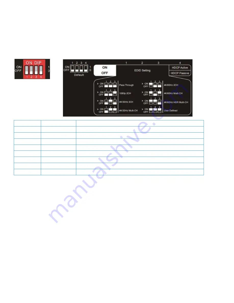
EDID Management
Switches 1, 2, 3
Ocean Matrix OMX—01HMBT0009
Ocean Matrix
www.oceanmatrix.com
The source device obtains its EDID from the first connected display. To ensure video resolution compatibility among multiple displays, set the EDID to a fixed
value using the DIP switch. See the bottom of the device for settings.
ON Position = 1
OFF Position = 0
Switch Setting Video Resolution
Audio Format
000
001
1080P
2CH (LPCM 2 CH)
010
3840x2160@30Hz
2CH (LPCM 2 CH)
011
3840x2160@30Hz
Multi-CH (LPCM 8CH, Dolby TrueHD, DTS-HD , Dolby Digital5.1, DTS 5.1, Dolby Digital Plus)
100
3840x2160@30Hz
22CH (LPCM 2 CH)
101
3840x2160@30Hz
Multi-CH (LPCM 8CH, Dolby TrueHD, DTS-HD , Dolby Digital5.1, DTS 5.1, Dolby Digital Plus)
110
3840x2160@30Hz HDR Multi-CH (PCM 2CH, PCM5.1, Dolby Digital 5.1, DTS 2CH
111
User-Defined EDID
Refer to Information Below
Pass Through
Pass Through
User-Defined EDID
The specific EDID can be customized by following the steps below:
1. Rename the user-defined EDID according the following format. EC_xx_xxxxx_xxxx_xxx.bin
EC: Fixed value
xx: EDID ID. It is “15”.
xxxxx: Video resolution.
xxxx: Refresh rate.
xxx: Audio format.
Example: EC_15_3840x2160_60Hz_ Dolby.bin
1. Connect the FW port of the transmitter to the PC with a USB cable, and then power on the transmitter. The PC will automatically detect a virtual disk:
BOOTDISK.
2. Double-click to open the disk, to a file READY.TXT
3. Copy the user-defined EDID (such as EC_15_3840x2160_60Hz_Dolby.bin) to the “BOOTDISK” disk.
4. Reopen the disk to check the filename READY.TXT. If the filename automatically becomes “SUCCESS.TXT” then the user-defined EDID was imported
into the transmitter and saved as its corresponding EDID ID successfully.
5. Remove the USB cable, and then reboot the transmitter.
6. Now the new EDID can be ready by setting the DIP switch status to 111.
To set HDCP Active Mode, put Switch 4 in the ON position. The HDMI output will be HDCP 1.4, if the input video has HDCP content. If no HDCP
content, there will be no HDCP output.
To set HDCP Passive Mode, put Switch 4 in the OFF position. The unit automatically follows the HDCP version of source device.
HDCP Switch 4


