background image

2

SECTION 1: INTRODUCTION

NOTES: 

• 

Lens

: The camera accommodates a standard C or CS mount lens. 

• 

Menu operation buttons

: Slide the side panel back to access these buttons.  See “3.1 Menu operation” on page 8  for more 

information. 

• 

Mounting bracket

: The mounting bracket can be attached to the top-side or under-side of the camera. 

• 

Flange back (back focus) set screw

:  Used to lock the flange back. The adjustment is required only when a lens without 

focus-adjusting mechanism is mounted, or when a lens with adjusting mechanism is mounted and more accurate focus that 
is needed.

• 

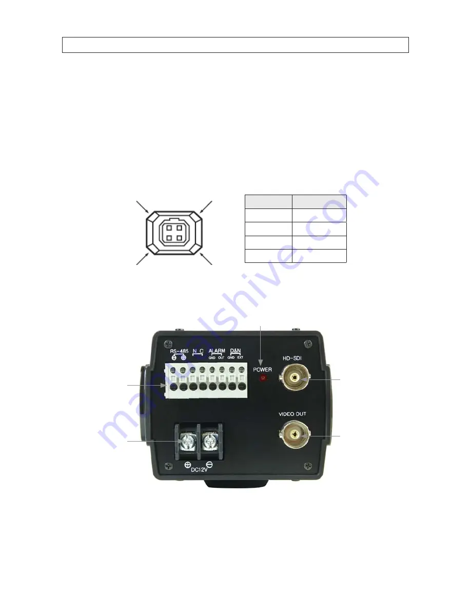
Lens iris output connector

:  4-pin connector used to send the Iris control signal and power supply to an auto-iris type lens

4

2

3

1

Pin

DC -type lenses

1

Damping -

2

D

3

Drive +

4

Drive -

1.1.1  Camera back panel

External device  

connections

Power indicator

Power input  

terminals

HD-SDI connector

Video out connector

BLK-HDC10 back connectors

Содержание Black BLK-HDC10

Страница 1: ...Megapixel Full HD C mount Box Camera User Manual Please read this manual before using your camera and always follow the instructions for safety and proper use Save this manual for future reference BL...

Страница 2: ...ich case the user will be required to correct the interference at his own expense LEGAL NOTICE Observint Technologies Observint products are designed to meet safety and performance standards with the...

Страница 3: ...explosion if battery is incorrectly replaced Replaced only with the same or equivalent type recommended by the manufacturer Dispose of used batteries according to the manufacturer s instructions A sui...

Страница 4: ...adhered to 8 Do not install near any heat sources such as radiators heat registers stoves or other apparatus including amplifiers that produce heat 9 Do not defeat the safety purpose of the polarized...

Страница 5: ...Camera components 1 1 2 What you need 3 SECTION 2 Installation 4 2 1 Camera installation bracket setup 4 2 2 Attach the lens 5 SECTION 3 Configuration Setup 8 3 1 Menu operation 8 3 2 CAMERA MODE 9 3...

Страница 6: ...vi...

Страница 7: ...ight for a 2 dB improvement in the signal to noise ratio The result is a brighter picture with less noise even in low light High definition video HDcctv security cameras deliver true 1080p or 720p HD...

Страница 8: ...w Used to lock the flange back The adjustment is required only when a lens without focus adjusting mechanism is mounted or when a lens with adjusting mechanism is mounted and more accurate focus that...

Страница 9: ...information Alarm Output Terminal ALARM OUT COM Connect to the alarm input of an external device When motion is detected 3 3 Vdc is applied to the Alarm Out Gnd terminals RS 485 Communication Connect...

Страница 10: ...n the upper side or the underside of the camera Normally the bracket is factory installed on the underside of the camera If the camera will attach to the mounting bracket on the upper side remove the...

Страница 11: ...ng cap from the lens mounting ring as shown below Lens mounting ring Cap 2 Carefully screw the lens assembly clockwise onto the lens mounting ring until it is fully seated Tighten until snug Lens moun...

Страница 12: ...minal block on the back of the camera as needed See 1 1 1 Camera back panel on page 2 for more information Wire these devices to the camera in compliance with local codes 7 Connect the HD SDI connecto...

Страница 13: ...cal setup monitor 13 While observing the image from the camera on the monitor adjust the camera for the desired field of view a Adjust the mounting bracket to center the field of view in the camera im...

Страница 14: ...on to select an item or adjust the parameters Right button u Moves the cursor to the right in the menu Use this button to select or adjust the parameters of the selected item The parameter changes eac...

Страница 15: ...mally OFF DSS Select maximum DSS Digital Slow Shutter OFF x2 x3 x4 AGC Select Auto Gain Control OFF ON WDR BLC Select WDR Wide Dynamic Range or BLC Back Light Compensation NOTE When WDR is ON ACE and...

Страница 16: ...area POS X Adjust the window X Axis position POS Y Adjust the window Y Axis position SIZ X Adjust the window X Axis size SIZ Y Adjust the window Y Axis size IR COMP Compensate when IR hunting happens...

Страница 17: ...evel 0 10 steps MIRROR Select a flip mode OFF H V H V H You can flip the picture horizontally on the screen V You can flip the picture vertically on the screen H V You can flip the picture horizontall...

Страница 18: ...nly with IP camera Set to OFF GAMMA Set gamma level for best display 3 6 INTELLIGENT PRIVACY Hide an area you want to hide on the screen OFF ON MASK Select mask area number 0 31 MODE Set up masking ar...

Страница 19: ...0 10 NOTE When DEFOG is On ACE and WDR BLC function can not turn on SYSTEM Select NTSC or PAL NTSC PAL HD FORMAT Select Digital output 1080P or 720P 1080P 720P PG Select Color pattern generator OFF ON...

Страница 20: ...14 SECTION 3 CONFIGURATION SETUP 3 8 DISPLAY DISP SEL Select display item ID OFF ON TITLE OFF ON EZOOM OFF ON SET TITLE Select camera title menu Text edit SetTitlecharacterset on screen...

Страница 21: ...80 x 720 720p 60 fps Analog 700 TVL Min Illumination Color 1 0 lux B W 0 5 lux Color DSS 0 002 lux BW DSS 0 001 lux Video output HD SDI Analog NTSC PAL without WDR S N ratio 50 dB AGC off Function MOD...

Страница 22: ...SC PAL HD FORMAT 1080p 720p PG Off On CVBS Off On COMM ID 1 255 Baud rate 2400 4800 9600 19200 38400 57600 115200 protocol PELCO P PELCO D UPDATE DEFAULT ON DONE Language English OSD Text 0 9 A Z a z...

Страница 23: ...have an intermediate device set the 75 Hi Z properly and check the terminals If an auto iris lens is being used adjust the brightness level The MOTION DETECTION function is not working Is MOTION DETEC...

Страница 24: ...18 APPENDIX B CAMERA DIMENSIONS APPENDIX B Camera Dimensions 5 45 41 2 15 1 1 4 20 UNC 1 86 55 2 78...

Отзывы: