background image

17 | EN

Screw-on cable tray systems

System overview

4 1 4 

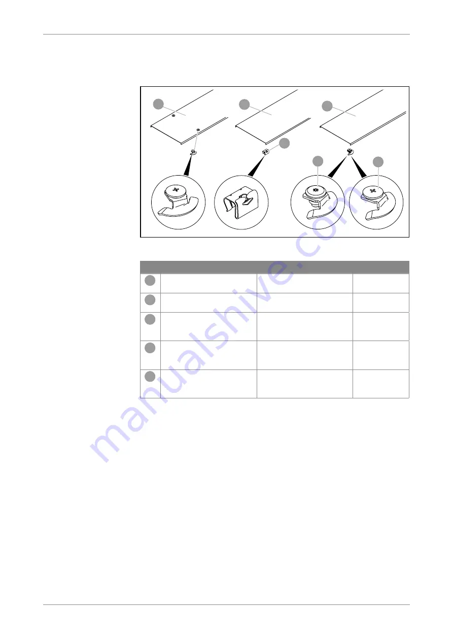
Cover for cable trays

Covers for cable trays are available without fastening material or with 

pre-mounted turn buckles.

1

4

5

2

3

2

Fig  10:  

Covers with fastening material for cable trays

No  Designation /type

Function

Application

1

Cover with pre-mounted 

turn buckles

Protection against weath-

ering and dirt

100–600 mm 

tray width

2

Cover, unperforated

Protection against weath-

ering and dirt

100–600 mm 

tray width

3

DK DRLU cover clamp

Cover fastening, mounting 

on the cover with clamps

Perforated and 

unperforated 

covers

4

DRL H S turn buckle

Cover fastening, mounting 

on the cover with screws

Perforated and 

unperforated 

covers

5

DRL H turn buckle

Cover fastening, mounting 

on the cover with rivets

Perforated and 

unperforated 

covers

Tab  9:  

Overview of covers and fastening material

Содержание 6053106

Страница 1: ...OBO Bettermann Holding GmbH Co KG Mounting instructions Screw on cable tray systems...

Страница 2: ...2021 OBO Bettermann Holding GmbH Co KG Screw on cable tray systems Mounting instructions...

Страница 3: ...1 5 2 Mounting the joint plate 22 5 3 Applying the edge protection strip 22 5 4 Connecting cable trays 23 5 4 1 Creating a straight connection 23 5 4 2 Creating an angled connection 28 5 4 3 Creating...

Страница 4: ...4 EN OBO Bettermann Table of contents 6 Maintaining the system 61 7 Dismantling the system 61 8 Disposing of the system 61 9 Technical data 62...

Страница 5: ...arranty claims for damage caused through non obser vance of these instructions Any images are intended merely as examples Mounting results may look different In these instructions cables and lines are...

Страница 6: ...Clamp_fastening_systems pdf 2 Correct use The screw on cable tray systems are used to support and route all kinds of cables taking the approved load values into account Depending on the corrosion prot...

Страница 7: ...Personal protective equipment List of personal protective equipment to be used Use hand protection Wear eye protection 3 3 Personal tools List of required tools Angle grinder Drill battery operated sc...

Страница 8: ...s steel A2 A4 surfaces MKS medium duty cable tray system SKS heavy duty cable tray system DKS perforated cable tray system EKS extra heavy duty cable tray system IKS industrial cable tray system The s...

Страница 9: ...straight and angle connector Screwed straight connec tion and horizontal change of direction Cable tray height 35 and 60 mm 3 RLVK straight connector Screwed straight connec tion and horizontal change...

Страница 10: ...mm Creation of 90 bend hori zontal 100 300 mm tray width 2 Fastening material FRS truss head bolt with combi nation nut Fastening to cable tray 100 600 mm tray width 3 RB 90 90 bend radius 150 mm Cre...

Страница 11: ...mm Creation of 45 bend hori zontal 100 300 mm tray width 2 Fastening material FRS truss head bolt with combi nation nut Fastening to cable tray 100 600 mm tray width 3 RB 45 45 bend radius 150 mm Crea...

Страница 12: ...erial Creation of 90 branch 100 300 mm tray width 2 RAA add on tee with connector perforation Creation of 90 branch 400 600 mm tray width 3 Connector perforation Fastening material retainer 400 600 mm...

Страница 13: ...ing material Creation of 90 branch 100 300 mm tray width 2 Fastening material FRS truss head bolt with com bination nut Fastening to cable tray 100 600 mm tray width 3 RT T branch piece with connector...

Страница 14: ...ial Creation of 90 branch 100 300 mm tray width 2 Fastening material FRS truss head bolt with com bination nut Fastening to cable tray 100 600 mm tray width 3 RK cross over with connector perforation...

Страница 15: ...ation type Function Application 1 Vertical bend rising radius 180 mm Creation of 90 vertical bend rising vertically 100 600 mm tray width 2 Vertical bend falling radius 120 mm Creation of 90 bend fall...

Страница 16: ...d element Compensation of height offset Creation of vertical bends with flexible radii 100 600 mm tray width 2 Half adjustable connector Connection of adjustable bend element with cable tray 100 600 m...

Страница 17: ...les Protection against weath ering and dirt 100 600 mm tray width 2 Cover unperforated Protection against weath ering and dirt 100 600 mm tray width 3 DK DRLU cover clamp Cover fastening mounting on t...

Страница 18: ...ting covers All the available articles versions models are listed in the chapter 9 Technical data on page 62 1 3 2 Fig 11 Cover for fittings No Designation type Function Application 1 DFB cover 45 ben...

Страница 19: ...es or functions All tray types 3 Edge protection strip Cover of cut cable tray edges protection against cable damage All tray types 4 Joint plate Connection of cable tray bases at the joint All tray t...

Страница 20: ...own can be mounted on both perforated and unperforated cable trays If unperforated cable trays are cut then the connector perforation must be re drilled When mounting the FRS truss head bolts and SKS...

Страница 21: ...njuries to eyes and hands Wear protective glasses and gloves Deburr cut edges 1 Cut cable trays to the desired length e g using an angle grinder 2 Deburr cut edges Note In the case of cable trays for...

Страница 22: ...n mounted The joint plate is fastened with FRS M6 truss head bolts and combination nuts Fig 13 Mounting the joint plate 1 Place the joint plate centrally on the joint area of the cable trays 2 Screw o...

Страница 23: ...ate rises or drops Risk of damage Screws can damage cables Always pass fastening screws through the rail from the inner side of the cable tray and secure with combination nuts on the outer side of the...

Страница 24: ...tors Straight connection with RLVK straight connector The RLVK straight connector is used with the cable tray heights 35 and 60 mm The connector is fastened with FRS M6 truss head bolts and combinatio...

Страница 25: ...25 EN Screw on cable tray systems Mounting Fig 18 Screw on the RLVK straight connector 2 Screw on the straight connector...

Страница 26: ...ss head bolts and combination nuts To avoid transverse bending at higher loads a joint plate must be used for tray widths of 400 mm or more Up to a tray width of 300 mm the mounting of the joint plate...

Страница 27: ...tray heights 35 and 60 mm The connector is screwed on with FRS M6 truss head bolts and combination nuts Fig 21 Inserting RWVL straight and angle connectors 1 Insert the straight and angle connectors...

Страница 28: ...th the cable tray heights 35 and 60 mm The connector is screwed on with FRS M6 truss head bolts and combination nuts Fig 23 Cutting the cable trays to create angles 1 Measure the angle and draw it ont...

Страница 29: ...29 EN Screw on cable tray systems Mounting Fig 25 Screwing on the RWVL straight and angle connector 1 Insert the angle connector on the inner sides of the rail 2 Screw on the angle connector...

Страница 30: ...he connector is screwed on with FRS M6 truss head bolts and combination nuts W W 2x50 50 Fig 26 Notching out cable tray rails for WKV angle connectors 1 Notch out the cable tray rail with the dimensio...

Страница 31: ...FRS M6 truss head bolts and combination nuts 45 x x Fig 28 Cutting the cable trays for the REV corner connector 1 Cut the cable trays at a 45 angle and notch out the cable tray rails with the dimensi...

Страница 32: ...ition floor end plates are mounted to avoid cable damage due to sharp edges Connectors and floor end plates are screwed on with FRS M6 truss head bolts and combination nuts 1 2 3 Fig 30 RGV adjustable...

Страница 33: ...r to the cable tray 3 Insert the adjustable connector in the inner sides of the rail 4 Screw on the adjustable connectors Fig 33 Tightening the hinge screw 5 Adjust the angle on the adjustable connect...

Страница 34: ...34 EN OBO Bettermann Mounting Fig 34 Tighten the securing screw 7 Screw on the adjustable connectors 8 Screw on the locking screw in the slot or other available drill hole...

Страница 35: ...ferent support systems is shown in special mounting instruc tions see 1 6 Applicable documents on page 6 Risk of the support system falling If fittings are not supported cable loads can become too hea...

Страница 36: ...support element must additionally be mounted under the fitting when the system is fully assigned With fittings of a width of 400 mm an additional support element must always be mounted under the fitt...

Страница 37: ...unted on the fitting with the supplied FRS M6 truss head bolts and combination nuts The WKV angle connector is mounted in the same way on all fittings with a width of 100 300 mm Fig 37 WKV angle conne...

Страница 38: ...0 300 mm cable tray width 1 With unperforated cut cable trays pre drill the connector perforation for angle connectors and the external connection of cable tray and fitting 2 Mount the WKV angle conne...

Страница 39: ...re mounted with RLVL 85 110 straight connectors and a joint plate The straight connector and the joint plate are screwed on with FRS M6 truss head bolts and combination nuts Fig 41 Pre drilling the mo...

Страница 40: ...ctor perforation and are screwed on with FRS M6 truss head bolts and combination nuts Fig 43 Mounting a falling vertical bend Fig 44 Mounting a rising vertical bend 1 Push the vertical bend onto the f...

Страница 41: ...forated cut cable trays pre drill the connector perforation for angle connectors and joint plates 2 Mount the WKV angle connector on the add on tee 50 50 W 2x50 B Fig 45 Notching out a cable tray rail...

Страница 42: ...42 EN OBO Bettermann Mounting Fig 47 Screwing the branching cable tray to the add on tee 6 Push the branching cable tray onto the straps of the angle connector 7 Screw on the cable tray...

Страница 43: ...d with RLVL 85 110 straight and angle connec tors The straight and angle connectors are screwed on with FRS M6 truss head bolts and combination nuts W 2x150 B 150 150 Fig 48 Notching out a cable tray...

Страница 44: ...l the connector perforation in the cable tray base for the add on tee 7 Screw the add on tee to the cable tray rail and cable tray base 8 Push the RLVK or RLVL straight and angle connector of the bran...

Страница 45: ...ut WKV angle connectors With connector 100 300 mm cable tray width 1 Mount the WKV angle connector on the T branch piece Fig 51 T branch piece with WKV angle connectors Fig 52 Pushing the cable trays...

Страница 46: ...46 EN OBO Bettermann Mounting Fig 53 Screwing on the T branch piece 3 Screw the cable trays to the T branch piece...

Страница 47: ...gle connectors The straight and angle connectors are screwed on with FRS M6 truss head bolts and combination nuts Fig 54 T branch piece with RLVL straight and angle connectors and joint plates Fig 55...

Страница 48: ...e available with or without WKV angle connectors With connector 100 300 mm cable tray width 1 Mount the WKV angle connector at the cross over Fig 56 Cross over with WKV angle connectors Fig 57 Pushing...

Страница 49: ...49 EN Screw on cable tray systems Mounting Fig 58 Screwing on a cross over 3 Screw the cable trays to the cross over...

Страница 50: ...ted with RLVK 35 60 straight and angle connectors Cross overs with a side height of 85 or 110 mm are mounted with RLVL 85 110 straight and angle connect ors The straight and angle connectors are screw...

Страница 51: ...16 hinge screws and locking screws The angles should be flexible Floor end plates are mounted at the ends of the cable trays in order to avoid cable damage Fig 61 Adjustable bend elements with half ad...

Страница 52: ...e inner sides of the rail Fig 64 Mounting adjustable bend elements 4 Fasten adjustable bend elements to adjustable connectors with SKS M8x16 hinge screws 5 Adjust the angle 6 Screw on the locking scre...

Страница 53: ...ead bolts and combina tion nuts Mounting a reducer profile 1 With unperforated cut cable trays pre drill the connector perforation for connectors reducer profiles and joint plates Fig 65 Bending adjus...

Страница 54: ...54 EN OBO Bettermann Mounting Fig 67 Screwing on the joint plate and RWVL straight and angle connector 5 Screw on the joint plate...

Страница 55: ...le trays pre drill mounting perforations Fig 68 Bending straps 2 Bend the straps on the end closure inwards by 90 Fig 69 Mounting an end closure 3 Push the end closure into the cable tray In so doing...

Страница 56: ...cable trays pre drill mounting perforations 2 Screw on the barrier strip 5 7 Creating equipotential bonding Note We recommend including the screw on cable tray system in the equi potential bonding Th...

Страница 57: ...es 5 8 1 Mounting the cover with cover clamp 50 Fig 72 Clamping the cover clamp to the cover 1 Clamp the cover clamp to the edge of the cover Distance from the front edge at least 50 mm 2x 2x 2x 3000...

Страница 58: ...58 EN OBO Bettermann Mounting Fig 74 Snap on the cover 3 Snap the cover onto cable tray rails using cover clamps...

Страница 59: ...the cable tray using pre mounted turn buckles in the same manner as with those installed at a later date Mounting the turn buckle B B DRL B 27 mm DBKR B 27 mm WDRL B 38 mm WKLD B 58 mm 16 5 mm Fig 75...

Страница 60: ...ith Helix turn buckle 5 Mount at least 3 x 2 turn buckles for each 3 000 mm of cover length 6 Position the cover on the cable tray 7 Lock the turn buckle button on the cable tray using a screwdriver 5...

Страница 61: ...connection to the overall equipotential bonding must be continually intact and thus checked regularly 7 Dismantling the system All the elements of the cable tray systems are dismantled in the reverse...

Страница 62: ...e tray MKS 630 FS 60 300 FS 6055303 MKS cable tray MKS 640 FS 60 400 FS 6055400 MKS cable tray MKS 650 FS 60 500 FS 6055508 MKS cable tray MKS 660 FS 60 600 FS 6055524 MKS cable tray MKS 610 FT 60 100...

Страница 63: ...407 SKS cable tray SKS 650 FS 60 500 FS 6056504 SKS cable tray SKS 660 FS 60 600 FS 6056601 SKS cable tray SKS 610 FT 60 100 FT 6056636 SKS cable tray SKS 615 FT 60 150 FT 6056644 SKS cable tray SKS 6...

Страница 64: ...10 100 FT 6061605 SKS cable tray SKS 120 FT 110 200 FT 6061621 SKS cable tray SKS 130 FT 110 300 FT 6061656 SKS cable tray SKS 140 FT 110 400 FT 6061672 SKS cable tray SKS 150 FT 110 500 FT 6061702 SK...

Страница 65: ...T 6056776 EKS cable tray EKS 620 FT 60 200 FT 6056792 EKS cable tray EKS 630 FT 60 300 FT 6056806 EKS cable tray EKS 640 FT 60 400 FT 6056970 EKS cable tray EKS 650 FT 60 500 FT 6056989 EKS cable tray...

Страница 66: ...traight and angle connector 110 RLVL 110 FT 110 FT 6067913 Straight and angle connector 110 RLVL 110 A2 110 A2 6067948 Adjustable connector 35 RGV 35 FS 35 FS 7082002 Adjustable connector 35 RGV 35 FT...

Страница 67: ...45 bend 60 RB 45 630 FS 60 300 FS 6043798 45 bend 60 RB 45 610 FT 60 100 FT 7066112 45 bend 60 RB 45 615 FT 60 150 FT 7066158 45 bend 60 RB 45 620 FT 60 200 FT 7066228 45 bend 60 RB 45 630 FT 60 300...

Страница 68: ...end 110 RB 45 120 FT 110 200 FT 7068212 45 bend 110 RB 45 130 FT 110 300 FT 7068328 45 bend 110 RB 45 140 FS 110 400 FS 7000685 45 bend 110 RB 45 150 FS 110 500 FS 7000707 45 bend 110 RB 45 155 FS 110...

Страница 69: ...bend 60 RBU 90 650 A4 60 500 A4 7134294 90 bend 60 RBU 90 660 A4 60 600 A4 7134296 90 bend 85 RB 90 810 FS 85 100 FS 7001762 90 bend 85 RB 90 820 FS 85 200 FS 7001789 90 bend 85 RB 90 830 FS 85 300 F...

Страница 70: ...d on tee 60 RAA 620 FT 60 200 FT 7121205 Add on tee 60 RAA 630 FT 60 300 FT 7121318 Add on tee 60 RAA 610 A2 60 100 A2 7136120 Add on tee 60 RAA 620 A2 60 200 A2 7136133 Add on tee 60 RAA 630 A2 60 30...

Страница 71: ...500 FS 7002726 Add on tee 110 RAA 155 FS 110 550 FS 7002734 Add on tee 110 RAA 140 FT 110 400 FT 7123396 Add on tee 110 RAA 150 FT 110 500 FT 7123507 Add on tee 110 RAA 155 FT 110 550 FT 7123558 T bra...

Страница 72: ...FT 7113315 Cross over 60 RK 640 FT 60 400 FT 7113404 Cross over 60 RK 645 FT 60 450 FT 7113463 Cross over 60 RK 650 FT 60 500 FT 7113501 Cross over 60 RK 660 FT 60 600 FT 7113609 Cross over 60 RK 675...

Страница 73: ...90 vertical bend falling 60 RBV 620 F FS 60 200 FS 7007063 90 vertical bend falling 60 RBV 630 F FS 60 300 FS 7007067 90 vertical bend falling 60 RBV 640 F FS 60 400 FS 7007071 90 vertical bend fallin...

Страница 74: ...alling 85 RBV 840 F FT 85 400 FT 7007283 90 vertical bend falling 85 RBV 850 F FT 85 500 FT 7007287 90 vertical bend falling 85 RBV 860 F FT 85 600 FT 7007291 90 vertical bend rising 110 RBV 110 S FS...

Страница 75: ...cal 60 RGBEV 615 FT 60 150 FT 7075154 Adjustable bend element vertical 60 RGBEV 620 FT 60 200 FT 7075200 Adjustable bend element vertical 60 RGBEV 630 FT 60 300 FT 7075308 Adjustable bend element vert...

Страница 76: ...rtical 110 RGBEV 140 FT 110 400 FT 7077408 Adjustable bend element vertical 110 RGBEV 150 FT 110 500 FT 7077505 Adjustable bend element vertical 110 RGBEV 160 FT 110 600 FT 7077972 Cover length 3 000...

Страница 77: ...uckle DRL 300 A4 300 A4 6052983 Cover with turn buckle DRL 400 A4 400 A4 6052984 Cover with turn buckle DRL 500 A4 500 A4 6052985 Cover with turn buckle DRL 600 A4 600 A4 6052986 Cover unperforated DR...

Страница 78: ...rforated DRLU 150 A4 150 A4 6052992 Cover unperforated DRLU 200 A4 200 A4 6052993 Cover unperforated DRLU 300 A4 300 A4 6052994 Cover unperforated DRLU 400 A4 400 A4 6052995 Cover unperforated DRLU 50...

Страница 79: ...9653 Cover for 90 bend DFB 90 100 DD 100 DD 7130511 Cover for 90 bend DFB 90 150 DD 150 DD 7130538 Cover for 90 bend DFB 90 200 DD 200 DD 7130546 Cover for 90 bend DFB 90 300 DD 300 DD 7130562 Cover f...

Страница 80: ...200 A4 200 A4 7136921 Cover for add on tee DFAA 300 A4 300 A4 7136929 Cover for add on tee DFAA 400 A2 400 A2 7136935 Cover for add on tee DFAA 500 A2 500 A2 7136943 Cover for add on tee DFAA 600 A2 6...

Страница 81: ...100 FS 7130805 Cover for 90 vertical bend rising DBV 150 S FS 150 FS 7130809 Cover for 90 vertical bend rising DBV 200 S FS 200 FS 7130813 Cover for 90 vertical bend rising DBV 300 S FS 300 FS 7130817...

Страница 82: ...end falling side height 60 DBV 60 100 F A4 100 A4 7130972 Cover for 90 vertical bend falling side height 60 DBV 60 200 F A4 200 A4 7130974 Cover for 90 vertical bend falling side height 60 DBV 60 300...

Страница 83: ...ide height 110 DBV 110 200 F DD 200 DD 7131560 Cover for 90 vertical bend falling side height 110 DBV 110 300 F DD 300 DD 7131564 Cover for 90 vertical bend falling side height 110 DBV 110 400 F DD 40...

Страница 84: ...BEB 400 A4 400 A4 7084147 Bottom end plate BEB 500 A4 500 A4 7084149 Bottom end plate BEB 600 A4 600 A4 7084151 Barrier strips Designation Type Side height mm Length mm Surface Item no Barrier strip T...

Страница 85: ...100 A2 100 A2 7070353 Joint plate SSLB 200 A2 200 A2 7070361 Joint plate SSLB 300 A2 300 A2 7070365 Joint plate SSLB 400 A2 400 A2 7070369 Joint plate SSLB 500 A2 500 A2 7070373 Joint plate SSLB 600 A...

Страница 86: ...er profile end closure RWEB 840 FS 85 400 FS 7110405 Reducer profile end closure RWEB 850 FS 85 500 FS 7110502 Reducer profile end closure RWEB 860 FS 85 600 FS 7110618 Reducer profile end closure RWE...

Страница 87: ...m no FRS truss head bolt with com bination nut FRSB 6x12 G M6 x 12 5 6 G 6406130 FRS truss head bolt with com bination nut FRSB 6x 12 F M6 x 12 5 6 F 6406122 FRS truss head bolt with com bination nut...

Страница 88: ...OBO Bettermann Holding GmbH Co KG P O Box 1120 58694 Menden GERMANY Customer Service Germany Tel 49 0 2373 89 1700 Fax 49 0 2373 89 1238 E mail export obo de www obo global OBORD 190629 06 2021...

Отзывы: