12
Since the FS-70 ULTIMATE
is intended to be started with an
electric starter, the addition of a spinner assembly for
centering the starter sleeve is desirable. In this case, optional
locknut sets are available from O.S. Propeller Locknut Set for
Spinner (Code No. 45810200) Propeller Locknut Set for Tru
Turn Spinner (Code No. 45810300).
PROPELLER & SPINNER ATTACHMENT
Ream the propeller shaft hole to 6.5mm bore with an
appropriate reamer, checking that the hole is exactly
centered.
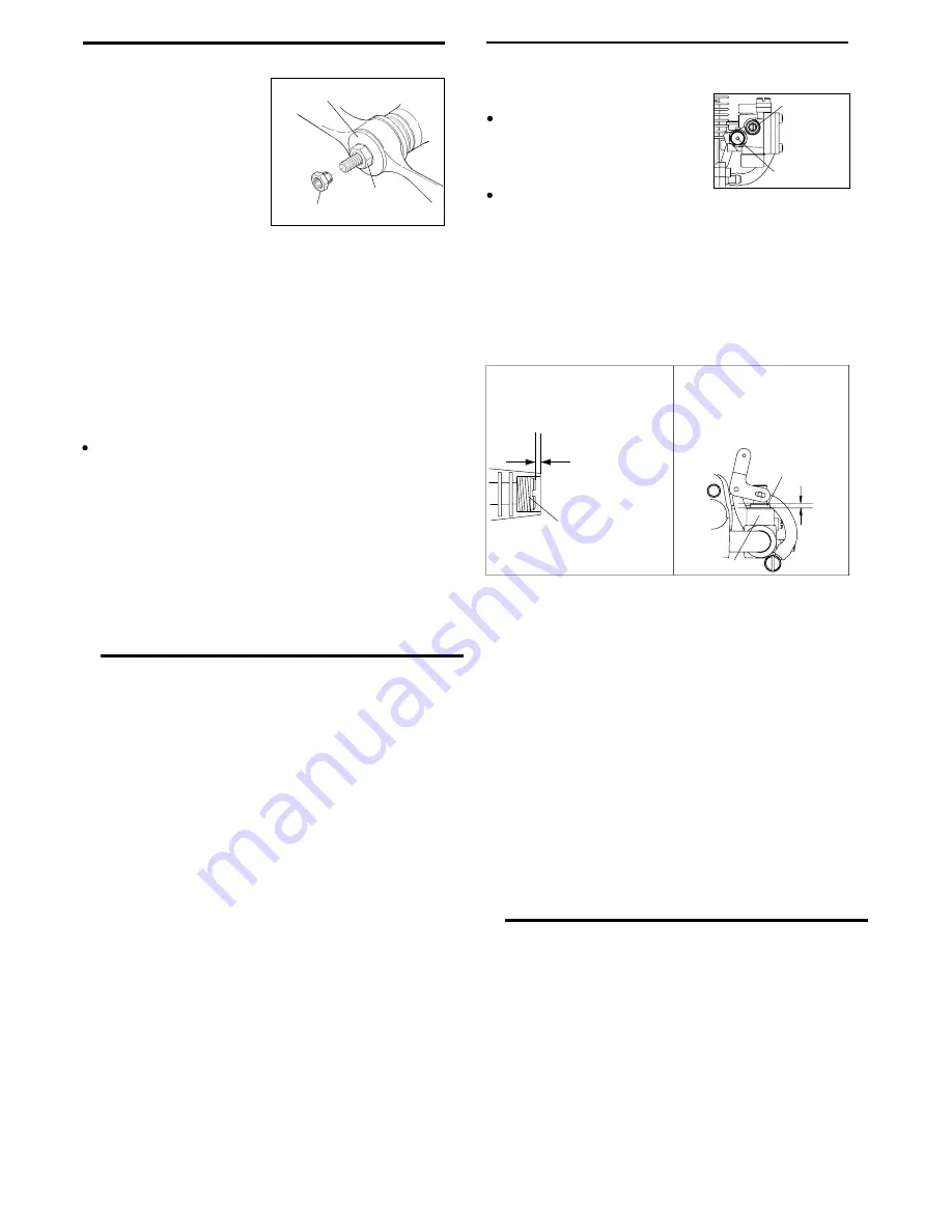
Install the prop to the engine shaft, followed by the retaining
washer and prop nut and tighten firmly with a 12mm
wrench.
There is a risk, particularly
with powerful four-stroke
engines, of the propeller flying
off if the prop nut loosens due
to detonation ("knocking") in
the combustion chamber when
the engine is operated too
lean, or under an excessively
heavy load.
Obviously, this can be very hazardous. To eliminate such
dangers, the O.S. Safety Locknut Assembly was devised.
Install this as follows:
Lock Nut
Propeller Washer
Propeller Nut
1.
2.
3.
Two adjustable controls are provided on these carburetors.
They are as follows:
TYPE 60U CARBURETOR
The Needle Valve
This is used to establish the fuel/air
mixture strength required for full
power when the throttle is fully open.
The sequence in which these controls are adjusted is
explained in the succeeding sections, under Starting,
Running-in and Idling Adjustment.
Add the special tapered and slotted locknut and secure
with a 10mm wrench while holding the prop nut with the
12mm wrench.
Needle Valve
Mixture
Control Screw
Spinners retained by a nose bolt cannot be used with this
Locknut.
The Mixture Control Screw
This is used to establish the mixture strength required for
steady idling and a smooth transition to medium speeds.
(The varying mixture strength required between part-throttle
and full-throttle running is automatically adjusted by coupled
movement of the throttle.)
BASIC POSITION OF THE
MIXTURE CONTROL SCREW
The basic position is
1/2 turn screwed in
position from the flat
with the body face.
Mixture Control Screw
IDLING POSITION OF THE
THROTTLE VALVE
The idling position is where
the throttle valve comes out
approx. 1mm from the body
face.
Carburetor Body
Throttle Valve
Approx. 1mm
13
STARTING
The FS-70 ULTIMATE
is not equipped with manual choke
controls, as they are intended for use with an electric starter only.
A high-torque electric starter not only makes starting the engine
much easier, it dispenses with the need for a choke valve by
turning the engine over fast enough to cause the fuel pump to
prime the cylinder automatically.
Starting procedure is as follows:
Check that the current to the glowplug is switched off.
Check that the polarity of the starter battery leads rotates the
engine counter-clockwise when viewed from the front.
Open the needle-valve approx. 2 turns from the fully closed
position and temporarily set the throttle in the fully open
position.
Apply the starter and press the starter switch for 5-6
seconds, or until fuel is seen to emerge from the exhaust
outlet, indicating that the cylinder is now primed.
Close the throttle-arm to within 15-20
°
of the fully closed
position and slowly turn the prop "backwards" (clockwise) by
hand until it is arrested by compression.This is to enable the
kinetic energy of the prop to subsequently assist the starter
through the compression stroke to start the engine.
Energize the glowplug and apply the starter. If the starter
fails to rotate the engine completely, this may be due to the
cylinder being over-primed, or to the starter battery being
insufficiently charged.
RUNNING-IN ("Breaking-in")
For long life and peak performance, every engine needs
special treatment when new, known as "running-in" or
"breaking-in". This is a process during which the engine is
operated under strictly controlled conditions at the beginning
of its life, in order to avoid the risk of immediate damage to
certain components through becoming overheated or stressed
and to help working surfaces to become smoothed and
aligned for maximum mechanical efficiency thereafter.
With some engines, this can require a tediously protracted
period of bench running, but, as O.S. engines are
manufactured to fine tolerances and from the finest quality
materials, a relatively brief running-in period is sufficient and
can be completed with the engine installed in the aircraft.
The recommended procedure is as follows :
1.
2.
3.
4.
5.
6.
Check these conditions and, instead of pressing the starter
button after applying the starter, have the starter spinning
before applying it to the engine, to give it a "running start".
When the engine starts, slowly open the throttle, leaving
the needle-valve at its rich starting setting to promote cool
running conditions.
However, if the engine slows down because the mixture is
excessively rich, the needle-valve may be closed a little to
speed it up until it runs evenly.
Now disconnect current to the glowplug and gradually close
the needle-valve so that the engine rpm increases. Make
adjustments to the needle in small steps. Abrupt changes
at this stage are likely to cause the engine to stall. Restart
the engine by simply applying the starter with the glowplug
re-energized and the throttle at its starting setting.
7.
8.


