UM11057
LPCXpresso845MAX
Rev. 1.0 — 9 June 2017
User Manual
Document information
Info
Content
Keywords
LPCXpresso845MAX, OM13097, LPC845, LPC844
Abstract
LPCXpresso845MAX User Manual
Страница 1: ...UM11057 LPCXpresso845MAX Rev 1 0 9 June 2017 User Manual Document information Info Content Keywords LPCXpresso845MAX OM13097 LPC845 LPC844 Abstract LPCXpresso845MAX User Manual...
Страница 2: ...ghts reserved User Manual Rev 1 0 9 June 2017 2 of 14 Contact information For more information please visit http www nxp com For sales office addresses please send an email to salesaddresses nxp com N...
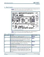
Страница 3: ...ble evaluation of and prototyping with the LPC84x family of MCUs Figure 1 shows the LPCXpresso845MAX Board The LPCXpresso845MAX board includes the following features Compatible with MCUXpresso IDE and...
Страница 4: ...SJ6 an ammeter can be installed between the pins of JP2 to measure current flow to the LPC845 Once SJ6 has been removed JP2 must either be installed or an ammeter in place in order for the LPC845 to b...
Страница 5: ...d be mounted on underside of PCB Section 4 P6 Once SJ18 has been removed P6 can be used to connect disconnect the LPC845 UART TX from the LPC11U35 debug probe VCOMM connection Section 5 3 P7 Once SJ17...
Страница 6: ...ding the debugger firmware image which will be called firmware bin follow these steps 1 With the board unpowered install jumper JP3 2 Power the board Using File Explorer or equivalent on Mac Linux pla...
Страница 7: ...MAX is connected to the host computer click Debug in the Quickstart panel The IDE will search for available debug probes Select the debug probe that appears for your board then click OK Note that the...
Страница 8: ...op bit no flow control Later production LPCXpresso845MAX boards have been programmed with an updated version of CMSIS DAP and a standard UART VCOM port It is recommended that the LPC11U35 firmware be...
Страница 9: ...ppings are shown in the tables below Some connections are shared with the LPCXpresso connector P3 as shown Table 2 Arduino expansion connector pin mappings Digital connector J1 J1 Pin Arduino signal L...
Страница 10: ...presso expansion connector follows the signal port mappings common to other MAX style LPCXpresso LPCXpresso V2 LPCXpresso CD and the original LPCXpresso boards Refer to the schematic for a full list o...
Страница 11: ...onnector pin 45 and to the cathode of the red user LED LPC845 pin PIO0_12 can be reconfigured by software so that the button can be used by an application as a general purpose button refer to the LPC8...
Страница 12: ...olutions web site for datasheet This device can drive 8 to 32 ohm speakers a 32 ohm speaker is supplied with the board and resistors have been selected to provide a reasonable volume level for musical...
Страница 13: ...suitable for use in life support life critical or safety critical systems or equipment nor in applications where failure or malfunction of an NXP Semiconductors product can reasonably be expected to...
Страница 14: ...tion 3 2 Board Layout 4 3 Getting Started 6 3 1 Debugger firmware update 6 3 2 Using the board with MCUXpresso IDE 6 3 3 Using LPCXpresso845MAX with 3rd Party IDEs 7 4 Debug Probe 8 4 1 Using an exter...