25
3.5 JTAG Connections
The S32G-VNP-GLDBOX has a 20-pin JTAG slot for S32G274A and a 10-pin JTAG slot for SJA1110. User
can connect a debugger (such as Lauterbach or S32 Debug Probe) to S32G274A through the 20-pin JTAG
slot. Similarly, user can connect a debugger to SJA1110 through the 10-pin JTAG slot.
3.6 Aurora Trace
The S32G-VNP-GLDBOX supports Aurora trace for S32G274A through the Aurora Trace slot (J57).
3.7 External Memory and Storage
The S32G-VNP-GLDBOX supports three kinds of external memories: LPDDR4, NOR Flash and SD/eMMC.
The table below shows the memory map of the DDR and NOR Flash on the S32G-VNP-GLDBOX.
Table 14. The memory map of the DDR and NOR Flash
Memory
Start
End
DDR(M7)
0x00_6000_0000
0x00_DFFF_FFFF
DDR(A53)
0x08_0000_0000
0x08_FFFF_FFFF
NOR Flash
0x00_0000_0000
0x00_1FFF_FFFF
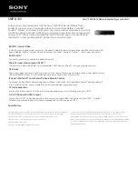
3.7.1 LPDDR4
S32G-VNP-GLDBOX has a single 1024 Meg x 32 (2 channels x 16 I/O) LPDDR4 SDRAM chip
(MT53D1024M32D4DT-046 AUT:D) for a total RAM memory of 4GB, and it supports inline-ECC and self-
refresh.
The DDR interfaces use power sources of 1.1VDC and 1.8VDC, which are respectively supplied by the
BUCK3 and LDO2 of the VR5510. The figure below shows the connection of LPDDR4.
DDR subsystem
S32G
LPDDR4
MT53D1024M32D4DT-
046 AUT:D
CKE_A[0:1]
CLK_A_P, CLK_A_N
CS_A[0:1]
CA_A[0:5]
DMI_A[0:1]
DQS[0:1]_A_P, DQS[0:1]_A_N
DQ_A[0:15]
CKE_B[0:1]
CLK_B_P, CLK_B_N
CS_B[0:1]
CA_B[0:5]
DMI_B[0:1]
DQS[0:1]_B_P, DQS[0:1]_B_N
DQ_B[0:15]
RESET
ZQ0
ZQ1
1.1V
CDT_CA_A
CDT_CA_B
1.1V
VDD1
VDD2
1.8V
VDDQ
1.1V
Figure 8. The connection of LPDDR4 SDRAM