


NXP Semiconductors
UM11099
PCAL6534 demonstration board OM13541
UM11099
All information provided in this document is subject to legal disclaimers.
© NXP B.V. 2019. All rights reserved.
User manual
Rev. 1.0 — 1 August 2019
13 / 29
Figure 7. Select the Expert Mode from Fm+ development board GUI (2 of 2)
Connect the hardware as described in
. All jumpers are in default setting and
device address is set to 0x46h on J8 (set ADDR = VDDI) for PCAL6534 demo board.
When you have correctly installed the software and the demonstration board hardware is
connected and recognized by the computer, start the Fm+ development board software.
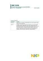
As shown in
, when the demonstration board hardware is correctly connected
to the USB port and the computer recognizes it, the message “USB-I2C Hardware
Detected” is displayed on the bottom of the window.
6.1 PCAL6534 output shifting pattern demo for all five ports
1. From the ‘Device’ drop-down menus select ‘Expert Mode’ as shown in
2. Copy the “output shifting pattern on all five ports” text file as shown below. From the
‘File’ drop-down menus select ‘Open’, and from the “open data file” window to select
the “output shifting pattern on all five ports” text file.
========================================================================
Expert Mode Data File
46,Write,Yes,200,0F,00,00,00,00,00,Comments: set all GPIOs as output ports
46,Write,Yes,200,05,FF,FF,FF,FF,FF,Comments: write registers 04,05,06 to set all
output ports to 1s
46,Write,Yes,200,05,FE,FE,FE,FE,FE,Comments: set bit0 to 0 in all five ports
46,Write,Yes,200,05,FD,FD,FD,FD,FD,Comments: set bit1 to 0 in all five ports