NXP Semiconductors OM13503 Скачать руководство пользователя страница 4


NXP Semiconductors 

UM10817 


OM13503, PCA8539 demo board 

UM10817 

All information provided in this document is subject to legal disclaimers. 

© NXP B.V. 2014. All rights reserved. 

User manual 

Rev. 1 — 3 September 2014 

4 of 13 


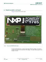
2.  Board description and layout 

In 

Fig 1

 the top view of the board is given. 


Fig 1. 

Top view of OM13503 demo board 

 
For best optical performance, remove the protective foil from the display. A red colored 

pull tape can be found on the bottom left of the display. The optimal viewing angle for this 

display is 6 o’clock. 


Содержание OM13503

Страница 1: ...board which can be used to demonstrate and evaluate the PCA8539 dot matrix driver This is a Chip On Glass LCD driver which can drive a dot matrix up to 100 18 dots with a display size of up to 7 The b...

Страница 2: ...ect to legal disclaimers NXP B V 2014 All rights reserved User manual Rev 1 3 September 2014 2 of 13 Contact information For more information please visit http www nxp com For sales office addresses p...

Страница 3: ...re compensation and it communicates either via a two line bidirectional I C bus or a four line bidirectional SPI bus This board was developed in order to provide a low cost tool to engineers wishing t...

Страница 4: ...served User manual Rev 1 3 September 2014 4 of 13 2 Board description and layout In Fig 1 the top view of the board is given Fig 1 Top view of OM13503 demo board For best optical performance remove th...

Страница 5: ...ltage provided to pin 1 of connector P2 will directly influence the display contrast and the optimal voltage can be selected Make sure that the voltage VLCD does not exceed the maximum limit of 16 V o...

Страница 6: ...be removed and R12 must be mounted If the internal oscillator is used the oscillator signal is available at connector pin CLK If an external oscillator signal is used this can be supplied to the LCD...

Страница 7: ...t can be connected to other debug targets such as a customer prototype Users can also use the LPCXpresso IDE with the Red Probe JTAG adapter from Code Red Technologies Refer to the Getting started wit...

Страница 8: ...OM13503 PCA8539 demo board UM10817 User manual UM10817 Rev 1 3 September 2014 All information provided in this document is subject to legal disclaimers 8 of 13 NXP B V 2014 All rights reserved Fig 3 S...

Страница 9: ...R I2CWrite 0b10000000 control byte I2CWrite 0x01 Initialize I2CWrite 0b10000000 control byte I2CWrite 0x02 OTP refresh delay_ms 20 I2CWrite PCA8539_ADDR I2CWrite 0b10000000 control byte I2CWrite 0x21...

Страница 10: ...s The documents listed below provide further useful information They are available at NXP s website www nxp com 1 LPCXPresso Getting started with NXP LPCXpresso 2 PCA8539 Product data sheet 3 UM10204...

Страница 11: ...for any assistance with applications or customer product design It is customer s sole responsibility to determine whether the NXP Semiconductors product is suitable and fit for the customer s applica...

Страница 12: ...l information provided in this document is subject to legal disclaimers NXP B V 2014 All rights reserved User manual Rev 1 3 September 2014 12 of 13 8 List of figures Fig 1 Top view of OM13503 demo bo...

Страница 13: ...es please send an email to salesaddresses nxp com Date of release 3 September 2014 Document identifier UM10817 9 Contents 1 Introduction 3 2 Board description and layout 4 2 1 Power Supply 5 2 2 Switc...

Страница 14: ...Mouser Electronics Authorized Distributor Click to View Pricing Inventory Delivery Lifecycle Information NXP OM13503UL...

Отзывы: