UM10706
All information provided in this document is subject to legal disclaimers.
© NXP B.V. 2013. All rights reserved.
User manual
Rev. 1 — 9 May 2013
12 of 16
NXP Semiconductors
UM10706
PCA9635 demonstration board OM13333
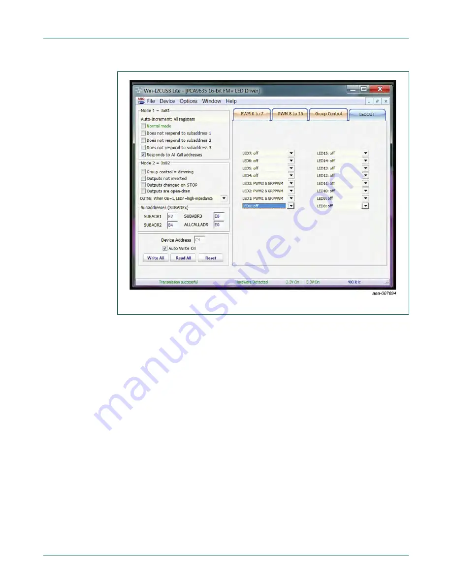
Fig 9.
Device configuration screen for LEDOUT


