


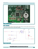


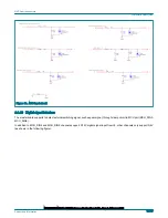


Figure 15. Digital input circuit
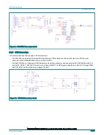
2.3.11 MSDI
The master board has a CD1030 to detect the closing and opening of multiple switch contacts and analog input signal. The input
signal is transferred to the MCU through DSPI2 with CS1.
As shown in the following figure, the master board enables SG0-SG9 as digital input, SP0-SP4 as analog input, these port is
connect to J8, and MCU read switch status via DPSI2, analog signal via MSDI_AMUX through eQADC channel 0 (ANA0).
NXP Semiconductors
Hardware User Guide
MPC5775B BMS Plus VCU Reference Design User Guide, Rev. 0, February 2020
Supporting Information
15 / 47


