NXP Semiconductors MIMXRT1010 EVK Скачать руководство пользователя страница 10

2.4 QSPI Flash

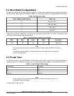
A 128 Mbit QSPI Flash is used on the MIMXRT1010 EVK Board. If the developer wants to boot from the QSPI Flash, the boot
device switch(SW8) settings should be: OFF, OFF, ON, OFF, as shown in 

Table 3

.

2.5 USB PHY Connector

The MIMXRT1010 contains a integrated USB 2.0 PHYs capable of connecting to USB host/device systems at the USB low-speed
(LS) rate of 1.5 Mbits/s, full-speed (FS) rate of 12 Mbits/s or at the USB 2.0 high-speed (HS) rate of 480 Mbits/s.

2.6 Audio input / output Connector

The Audio CODEC used on the MIMXRT1010 EVK Board is Wolfson’s Low Power, high quality Stereo Codec, WM8960.The
MIMXRT1010 EVK Board include one headphone interface (J11), one onboard MIC (P1), two speaker interfaces (J12, J13) , and
the SPDIF interface (J52 & J53, DNP). J11 is a 3.5 mm audio stereo headphone jack, which supports jack detect.

2.7 OpenSDA circuit (DAP-Link)

The OpenSDA circuit (CMSIS–DAP) is an open-standard serial and debug adapter. It bridges serial and debug communications
between a USB host and an embedded target processor.

CMSIS-DAP features a mass storage device (MSD) bootloader, which provides a quick and easy mechanism for loading different
CMSIS-DAP Applications such as flash programmers, run-control debug interfaces, serial-to-USB converters, and more. Two or
more CMSIS-DAP applications can run simultaneously. For example, run-control debug application and serial-to-USB converter
runs in parallel to provide a virtual COM communication interface while allowing code debugging via CMSIS-DAP with just single
USB connection.

For the MIMXRT1010 EVK Board, J41 is the connector between the USB host and the target processor. Jumper to serial
downloader mode to use stable DAP-Link debugger function. If developer wants to make OpenSDA going to the bootloader mode,
and press SW9 when power on. Meanwhile, the OpenSDA supports drag/drop feature for U-Disk. First, use the seral downloader
mode and drag/drop the image file to U-Disk. Then select QSPI Flash as boot device and reset the Board, the image will run.
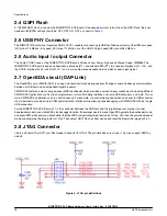
2.8 JTAG Connector

J55 is a standard 10-pin/1.27 mm Box Header Connector for JTAG. The pin definitions are shown in 

Figure 5

 support SWD by

default.

Figure 5. JTAG pin definitions

Specifications

MIMXRT1010 EVK Board Hardware User’s Guide, Rev. 0, 30/07/2019

10

NXP Semiconductors

Содержание MIMXRT1010 EVK

Страница 1: ...MIMXRT1010 EVK Board Hardware User s Guide NXP Semiconductors Document identifier MIMXRT1010EVKHUG User s Guide Rev 0 30 07 2019...

Страница 2: ...tor 10 2 6 Audio input output Connector 10 2 7 OpenSDA circuit DAP Link 10 2 8 JTAG Connector 10 2 9 Arduino and Motor control Expansion Port 11 2 10 ON OFF Button 12 2 11 Reset Button 12 2 12 USER Bu...

Страница 3: ...a large amount or resources in more specific designs Features of the MIMXRT1010 EVK board are shown in Table 1 Board features Table 1 Board features Processor NXP Processor MIMXRT1011 DCDC MPS MP2144...

Страница 4: ...contains the following items MIMXRT1010 EVK Board USB Cable Micro B 1 3 MIMXRT1010 EVK Board revision history Rev A Prototype Rev B Prototype Rev C Pilot Introduction MIMXRT1010 EVK Board Hardware Use...

Страница 5: ...the electrical design and practical considerations of the EVK Board and is organized to discuss each block in the following block diagram of the EVK board See Figure 1 Figure 1 Block diagram MIMXRT10...

Страница 6: ...uch as WLAN Bluetooth GPS Same as other i MX processors i MX RT1010 also has rich audio features including SPDIF and I2S audio interface The i MX RT1010 applications processor can be used in areas suc...

Страница 7: ...For more information about boot mode configuration see the System Boot chapter of the MIMXRT1010 Reference Manual For more information about MIMXRT1010 EVK boot device selection and configuration see...

Страница 8: ...PMIC_REQ_ON will be switched on to enable external DC DC to power up other power domains ON OFF button is used to switch ON OFF PMIC_REQ_ON to control power modes RESET button and WDOG output are use...

Страница 9: ...re supplies input voltage VDD_HIGH_IN 3 3 3 3 6 VDD_HIGH_IN supply voltage DCDC_IN 3 3 3 3 6 Power for DCDC VDD_SNVS_IN 2 4 3 3 6 Power for SNVS and RTC USB_OTG1_VBUS 4 4 5 5 5 Power for USB VBUS VDDA...

Страница 10: ...mass storage device MSD bootloader which provides a quick and easy mechanism for loading different CMSIS DAP Applications such as flash programmers run control debug interfaces serial to USB converte...

Страница 11: ...NC A4 ADC4 SDA NC A3 ADC3 NC A2 ADC2 NC A1 ADC1 NC A0 ADC0 Table 7 J56 D0 UART_RX NC D1 UART_TX ENC_I D2 INT0 NC D3 INT1 PWM OC2B NC D4 T0 XCK NC D5 TI PWM NC D6 AIN0 PWM OC0A NC D7 AIN1 PWM NC Table...

Страница 12: ...e causes the internal power management state machine to change state to ON In ON mode a short pressing generates an interrupt intended to be a software controllable power down An approximate 5 seconds...

Страница 13: ...levels 2 13 User Interface LED Indicator There are four LED status indicators located on the EVK Board The functions of these LEDs include Main Power Supply D27 Green DC 5V main supply is normal Off...

Страница 14: ...R 4 The PCB stack up information is shown in Table 10 Table 10 Board stack up information Layer Description Copper Oz Dielectric Thickness mil Top Signal Power GND 1 1 4 Dielectric FR4 56 Bottom Signa...

Страница 15: ...Files The schematics layout files and gerber files including Silkscreen can be downloaded from nxp com MIMXRT1010 EVK waiting for update MIMXRT1010 EVK Board Hardware User s Guide Rev 0 30 07 2019 NX...

Страница 16: ...11 EVK contents Item Description EVK Board EVK Board with processor memory interfaces etc USB Cable USB cable Micro B to Standard A Contents of the Evaluation Kit MIMXRT1010 EVK Board Hardware User s...

Страница 17: ...marizes the changes made to this document since the initial release Table 12 Revision history Revision number Date Substantive changes 0 07 2019 Initial release MIMXRT1010 EVK Board Hardware User s Gu...

Страница 18: ...design and operating safeguards to minimize the risks associated with their applications and products NXP the NXP logo NXP SECURE CONNECTIONS FOR A SMARTER WORLD COOLFLUX EMBRACE GREENCHIP HITAG I2C B...

Отзывы: