


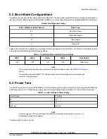


2.2 Boot Mode Configurations
The device has four boot modes (one is reserved for NXP use). The boot mode is selected based on the binary value stored in
the internal BOOT_MODE register. Switch (SW8-3 & SW8-4) is used to select the boot mode on the MIMXRT1010 EVK Board.
Table 2. Boot Mode pin settings
BOOT_MODE[1:0] (SW8-3 SW8-4)
BOOT Type
00
Boot From Fuses
01
Serial Downloader
10
Internal Boot
11
Reserved
Typically, the internal boot is selected for normal boot, which is configured by external BOOT_CFG GPIOs. The following
shows the typical Boot Mode and Boot Device settings.
Table 3. Typical Boot Mode and Boot Device settings
SW8-1
SW8-2
SW8-3
SW8-4
Boot Device
OFF
OFF
ON
OFF
QSPI Flash
For more information about boot mode configuration, see the System Boot chapter of the
For more information about MIMXRT1010 EVK boot device selection and configuration, see the main board
schematic. (waiting for update)
NOTE
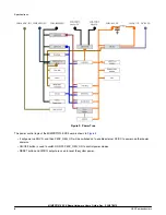
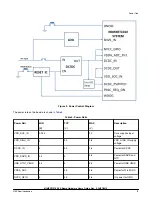
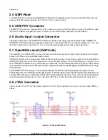
2.3 Power Tree
J41 and J9 can be used to supply the EVK Board. A DC 5V external power supply also can be used to supply the EVK Board by
connecting two pins in J1. Different power supply need to configure different Jumper setting of J1.
shows the details:
Table 4. Jumper settings of Power Supply
Power Supply
J1 Setting
J9
3-4
J41
1-2
External
5-6(7-8)
For some computers’ USB, it cannot support 500ma before establishing communication. In this case, it is
recommended to replace the computer.
NOTE
The power tree is shown in
.
Boot Mode Configurations
MIMXRT1010 EVK Board Hardware User’s Guide, Rev. 0, 30/07/2019
NXP Semiconductors
7