


Universal Serial Bus Interface
MCF5253 Reference Manual, Rev. 1
Freescale Semiconductor
24-49
24.8.3
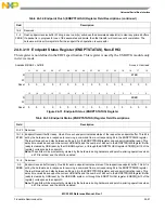
Isochronous (High-Speed) Transfer Descriptor (iTD)
The format of an isochronous transfer descriptor is illustrated in
for high-speed isochronous endpoints. All other transfer types should use queue structures. Isochronous
TDs must be aligned on a 32-byte boundary.
24.8.3.1
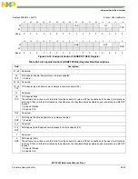
Next Link Pointer
The first DWord of an iTD is a pointer to the next schedule data structure.
31 30 29 28 27 26 25 24 23 22 21 20 19 18 17 16
15
14 13 12
11
10
9
8
7
6
5
4
3
2
1
0
Offset
Next Link Pointer
00
Typ
T
0x00
Status
1
1
Host controller read/write; all others read-only.
Transaction 0 Length
ioc
PG
2
2
These fields may be modified by the host controller if the I/O field indicates an OUT.
Transaction 0 Offset
0x04
Status
Transaction 1 Length
ioc
PG
Transaction 1 Offset
0x08
Status
Transaction 2 Length
ioc
PG
Transaction 2 Offset
0x0C
Status
Transaction 3 Length
ioc
PG
Transaction 3 Offset
0x10
Status
Transaction 4 Length
ioc
PG
Transaction 4 Offset
0x14
Status
Transaction 5 Length
ioc
PG
Transaction 5 Offset
0x18
Status
Transaction 6 Length
ioc
PG
Transaction 6 Offset
0x1C
Status
Transaction 7 Length
ioc
PG
Transaction 7 Offset
0x20
Buffer Pointer (Page 0)
EndPt
R
Device Address
0x24
Buffer Pointer (Page 1)
I/O
Maximum Packet Size
0x28
Buffer Pointer (Page 2)
Reserved
Mult
0x2C
Buffer Pointer (Page 3)
Reserved
0x30
Buffer Pointer (Page 4)
Reserved
0x34
Buffer Pointer (Page 5)
Reserved
0x38
Buffer Pointer (Page 6)
Reserved
0x3C
Figure 24-38. Isochronous Transaction Descriptor (iTD)
Table 24-38. Next Schedule Element Pointer
Bit
Name
Description
31–5 Link Pointer These bits correspond to memory address signals [31–5], respectively. This field points to another
Isochronous Transaction Descriptor (iTD/siTD) or Queue Head (QH).
4–3
–
Reserved. These bits are reserved and their value has no effect on operation. The software should initialize
this field to zero.
Содержание MCF5253
Страница 1: ...Document Number MCF5253RM Rev 1 08 2008 MCF5253 Reference Manual...
Страница 26: ...MCF5253 Reference Manual Rev 1 xxvi Freescale Semiconductor...
Страница 32: ...MCF5253 Reference Manual Rev 1 xxxii Freescale Semiconductor...
Страница 46: ...MCF5253 Introduction MCF5253 Reference Manual Rev 1 1 14 Freescale Semiconductor...
Страница 62: ...Signal Description MCF5253 Reference Manual Rev 1 2 16 Freescale Semiconductor...
Страница 98: ...Instruction Cache MCF5253 Reference Manual Rev 1 5 10 Freescale Semiconductor...
Страница 104: ...Static RAM SRAM MCF5253 Reference Manual Rev 1 6 6 Freescale Semiconductor...
Страница 128: ...Synchronous DRAM Controller Module MCF5253 Reference Manual Rev 1 7 24 Freescale Semiconductor...
Страница 144: ...Bus Operation MCF5253 Reference Manual Rev 1 8 16 Freescale Semiconductor...
Страница 176: ...System Integration Module SIM MCF5253 Reference Manual Rev 1 9 32 Freescale Semiconductor...
Страница 198: ...Analog to Digital Converter ADC MCF5253 Reference Manual Rev 1 12 6 Freescale Semiconductor...
Страница 246: ...DMA Controller MCF5253 Reference Manual Rev 1 14 18 Freescale Semiconductor...
Страница 282: ...UART Modules MCF5253 Reference Manual Rev 1 15 36 Freescale Semiconductor...
Страница 298: ...Queued Serial Peripheral Interface QSPI Module MCF5253 Reference Manual Rev 1 16 16 Freescale Semiconductor...
Страница 344: ...Audio Interface Module AIM MCF5253 Reference Manual Rev 1 17 46 Freescale Semiconductor...
Страница 362: ...I2 C Modules MCF5253 Reference Manual Rev 1 18 18 Freescale Semiconductor...
Страница 370: ...Boot ROM MCF5253 Reference Manual Rev 1 19 8 Freescale Semiconductor...


