


Advanced Technology Attachment Controller (ATA)
MCF5253 Reference Manual, Rev. 1
Freescale Semiconductor
23-29
•
ipbus_int. This interrupt is controlled by bits 3, 4, 5 and 6 of the interrupt registers. It will be
asserted if one of the 4 bits is set in the interrupt_pending register, while the same bit is set in the
interrupt_enable register. This interrupt goes to the CPU.
•
fifo_txfer_end_alarm. This interrupt is controlled by bit 7 of the interrupt registers. If ata_intrq1 is
set in both the interrupt enable and interrupt pending register, fifo_txfer_end_alarm will be
asserted. The goal of this interrupt is to inform the DMA that the running data transfer has ended.
This interrupt goes to the smart DMA.
These three registers have mostly the same bits. If a bit is set in the interrupt pending register, its interrupt
is pending, and will produce an interrupt if the same bit is set in the interrupt enable register. Some bits in
the interrupt pending register are sticky bits. Writing a ‘1’ to the corresponding bit in the interrupt clear
bit, will reset them.
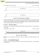
23.5.2.5.1
Interrupt_Pending Register
for illustration of valid bits in the Interrupt_Pending Register and
description of the bit fields.
Address MBAR2 + 0x828 (INTERRUPT_PENDING)
Access: User read-only
7
6
5
4
3
2
1
0
R
ata_intrq1
fifo_underflow
fifo_overflow
controller_idle
ata_irtrq2
W
Reset
0
0
1
0
–
–
–
1. Interrupts ata_intrq1 and ata_intrq2 only reset to 0 if during reset the interrupt input is low.
Figure 23-40. Interrupt_Pending Register
Table 23-11. Interrupt Pending Register Field Description
Field
Description
7
ata_intrq1
ATA interrupt request 1. This bit reflects the value of the ATA_INTRQ interrupt input. It is set in the interrupt
pending register when the drive interrupt is pending, cleared otherwise. When the bit is set in the interrupt
pending register, and the same bit is set in the interrupt enable register, fifo_txfer_end_alarm will be asserted,
signalling the DMA the end of the transfer. The interrupt clear register has no influence on this bit.
6
fifo_underflow
FIFO underfow. This bit reports FIFO underflow. Sticky bit. It is set in the interrupt pending register when there
is a FIFO underflow condition. It is cleared by writing a ‘1’ to this bit in the interrupt clear register. When the bit
is set in the interrupt pending register, and the same bit is set in the interrupt enable register, ipbus_int will be
active, signalling interrupt to the cpu.
5
fifo_overflow
FIFO overflow. This bit reports FIFO overflow. Sticky bit. It is set in the interrupt pending register when there is
a FIFO overflow condition. It is cleared by writing a ‘1’ to this bit in the interrupt clear register. When the bit is
set in the interrupt pending register, and the same bit is set in the interrupt enable register, ipbus_int will be
active, signalling interrupt to the cpu.
4
controller_idle
Controller Idle. This bit reports controller idle. It is set when the ATA protocol engine is idle, there is no activity
on the ATA bus. It is cleared when there is activity on the ATA bus. When the bit is set in the interrupt pending
register, and the same bit is set in the interrupt enable register, ipbus_int will be active, signalling interrupt to the
cpu. The interrupt clear register has no influence on this bit.
Содержание MCF5253
Страница 1: ...Document Number MCF5253RM Rev 1 08 2008 MCF5253 Reference Manual...
Страница 26: ...MCF5253 Reference Manual Rev 1 xxvi Freescale Semiconductor...
Страница 32: ...MCF5253 Reference Manual Rev 1 xxxii Freescale Semiconductor...
Страница 46: ...MCF5253 Introduction MCF5253 Reference Manual Rev 1 1 14 Freescale Semiconductor...
Страница 62: ...Signal Description MCF5253 Reference Manual Rev 1 2 16 Freescale Semiconductor...
Страница 98: ...Instruction Cache MCF5253 Reference Manual Rev 1 5 10 Freescale Semiconductor...
Страница 104: ...Static RAM SRAM MCF5253 Reference Manual Rev 1 6 6 Freescale Semiconductor...
Страница 128: ...Synchronous DRAM Controller Module MCF5253 Reference Manual Rev 1 7 24 Freescale Semiconductor...
Страница 144: ...Bus Operation MCF5253 Reference Manual Rev 1 8 16 Freescale Semiconductor...
Страница 176: ...System Integration Module SIM MCF5253 Reference Manual Rev 1 9 32 Freescale Semiconductor...
Страница 198: ...Analog to Digital Converter ADC MCF5253 Reference Manual Rev 1 12 6 Freescale Semiconductor...
Страница 246: ...DMA Controller MCF5253 Reference Manual Rev 1 14 18 Freescale Semiconductor...
Страница 282: ...UART Modules MCF5253 Reference Manual Rev 1 15 36 Freescale Semiconductor...
Страница 298: ...Queued Serial Peripheral Interface QSPI Module MCF5253 Reference Manual Rev 1 16 16 Freescale Semiconductor...
Страница 344: ...Audio Interface Module AIM MCF5253 Reference Manual Rev 1 17 46 Freescale Semiconductor...
Страница 362: ...I2 C Modules MCF5253 Reference Manual Rev 1 18 18 Freescale Semiconductor...
Страница 370: ...Boot ROM MCF5253 Reference Manual Rev 1 19 8 Freescale Semiconductor...