


Background Debug Mode (BDM) Interface
MCF5253 Reference Manual, Rev. 1
Freescale Semiconductor
20-27
the exact trigger response also programmable. The debug module programming model is accessible from
either the external development system using the serial interface or from the processor’s supervisor
programming model using the WDEBUG instruction.
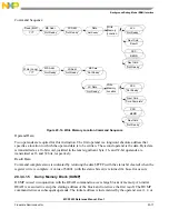
20.4.1
Theory of Operation
The breakpoint hardware can be configured to respond to triggers in several ways. The desired response
is programmed into the Trigger Definition Register (TDR). In all situations where a breakpoint triggers,
an indication is provided on the DDATA output port, when not displaying captured operands or branch
addresses, as shown in
The breakpoint status is also posted in the CSR.
The BDM instructions load and configure the desired breakpoints using the appropriate registers. As the
system operates, a breakpoint trigger generates a response as defined in the TDR. If the system can tolerate
the processor being halted, a BDM-entry can be used. With the TRC bits of the TDR
equal to $1, the
breakpoint trigger causes the core to halt as reflected in the PST = $F status.
NOTE
For PC breakpoints, the halt occurs before the targeted instruction is
executed. For address and data breakpoints, the processor may have
executed several additional instructions. As a result, trigger reporting is
considered imprecise.
If the processor core cannot be halted, the special debug interrupt can be used. With this configuration,
TRC bits of the TDR equal to $2, the breakpoint trigger is converted into a debug interrupt to the processor.
This interrupt is treated higher than the nonmaskable level 7 interrupt request. As with all interrupts, it is
made pending until the processor reaches a sample point, which occurs once per instruction. Again, the
hardware forces the PC breakpoint to occur immediately (before the execution of the targeted instruction).
This is possible because the PC breakpoint comparison is enabled at the same time the interrupt sampling
occurs. For the address and data breakpoints, the reporting is considered imprecise because several
additional instructions may be executed after the triggering address or data is seen.
Once the debug interrupt is recognized, the processor aborts execution and initiates exception processing.
At the initiation of the exception processing, the core enters emulator mode. After the standard 8-byte
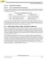
Table 20-17. DDATA[3:0], CSR[31:28] Breakpoint Response
DDATA[3:0], CSR[31:28]
Breakpoint Status
$000x
No Breakpoints Enabled
$001x
Waiting for Level 1 Breakpoint
$010x
Level 1 Breakpoint Triggered
$101x
Waiting for Level 2 Breakpoint
$110x
Level 2 Breakpoint Triggered
All other encodings are reserved for future use.
Содержание MCF5253
Страница 1: ...Document Number MCF5253RM Rev 1 08 2008 MCF5253 Reference Manual...
Страница 26: ...MCF5253 Reference Manual Rev 1 xxvi Freescale Semiconductor...
Страница 32: ...MCF5253 Reference Manual Rev 1 xxxii Freescale Semiconductor...
Страница 46: ...MCF5253 Introduction MCF5253 Reference Manual Rev 1 1 14 Freescale Semiconductor...
Страница 62: ...Signal Description MCF5253 Reference Manual Rev 1 2 16 Freescale Semiconductor...
Страница 98: ...Instruction Cache MCF5253 Reference Manual Rev 1 5 10 Freescale Semiconductor...
Страница 104: ...Static RAM SRAM MCF5253 Reference Manual Rev 1 6 6 Freescale Semiconductor...
Страница 128: ...Synchronous DRAM Controller Module MCF5253 Reference Manual Rev 1 7 24 Freescale Semiconductor...
Страница 144: ...Bus Operation MCF5253 Reference Manual Rev 1 8 16 Freescale Semiconductor...
Страница 176: ...System Integration Module SIM MCF5253 Reference Manual Rev 1 9 32 Freescale Semiconductor...
Страница 198: ...Analog to Digital Converter ADC MCF5253 Reference Manual Rev 1 12 6 Freescale Semiconductor...
Страница 246: ...DMA Controller MCF5253 Reference Manual Rev 1 14 18 Freescale Semiconductor...
Страница 282: ...UART Modules MCF5253 Reference Manual Rev 1 15 36 Freescale Semiconductor...
Страница 298: ...Queued Serial Peripheral Interface QSPI Module MCF5253 Reference Manual Rev 1 16 16 Freescale Semiconductor...
Страница 344: ...Audio Interface Module AIM MCF5253 Reference Manual Rev 1 17 46 Freescale Semiconductor...
Страница 362: ...I2 C Modules MCF5253 Reference Manual Rev 1 18 18 Freescale Semiconductor...
Страница 370: ...Boot ROM MCF5253 Reference Manual Rev 1 19 8 Freescale Semiconductor...


