


UM11158
All information provided in this document is subject to legal disclaimers.
© NXP B.V. 2018. All rights reserved.
User manual
Rev. 0.2 — 16 October 2018
7 of 20
NXP Semiconductors
UM11158
LPCXpresso55S69 Development Board
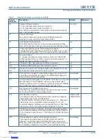
J4
Link2 (LPC43xx) force DFU boot.
Leave this jumper open (default) for Link2 to follow the normal boot
sequence. The Link2 will boot from internal flash if image is found
there. With the internal flash erased the Link2 normal boot sequence
will fall through to DFU boot.
Install this jumper to force the Link2 to DFU boot mode. Use this setting
to reprogram the Link2 internal flash with a new image (using the
LPCScrypt utility) or to use the MCUXpresso IDE with CMSIS-DAP
protocol.
Note that the Link2 flash is pre-programmed with a version of
CMSIS-DAP firmware by default.
Open
J5
Target processor selection for the on-board Debug Probe.
Jumper open (default) the LPC55S69 Target SWD interface enabled.
Normal operating mode where the Target SWD is connected to either
the on-board Link2 Debug Probe or an external Debug Probe.
Jumper shunted, the LPC55S69 Target SWD interface is disabled. Use
this setting only when the on-board Link2 Debug Probe is used to
debug an off-board target MCU.
Not installed
J6
USB host Vbus selection
Note that only one of USB0 or USB1 can be configured as a USB host
port at any given time (this is a board restriction, not a limitation of the
LPC55S69.)
Install jumper in position 1-2 for USB1 (High Speed) to provide Vbus
(i.e. enable USB host capability) (Default)
Install jumper in position 2-3 for USB0 (Full Speed) to provide Vbus (i.e.
enable USB host capability)
1-2 (USB1)
J7
USB host power control selection
This jumper selects routing of USB port power and overcurrent detect
from either the USB0 or USB1 ports of the LPC55S69. Note that only
one of USB0 or USB1 can be configured as a USB host port at any
given time (this is a board restriction, not a limitation of the LPC55S69.)
Leave open when using USB1 (High Speed) as a USB host (Default)
Install jumper for USB0 (Full Speed) to provide Vbus (i.e. enable USB
host capability)
Installed
(USB1)
J10
ISP boot jumper for LPC55S69. Installing this jumper ties port P0_5 to
ground, forcing the LPC55S69 into ISP mode whenever it is reset.
Open
n/a
J11
USB1 ID selection: USB1 ID is normally pulled to ground through a
100Kohm resistor. Installing this jumper connects USB1 ID to VBUS.
Open
J12
USB0 ID selection: USB1 IDis normally pulled to ground through a
100Kohm resistor. Installing this jumper connects USB0 ID to VBUS.
Open
P1
When open (default), the "Bridge" UART and SPI connections from the
Link2 probe are driven to the LPC55S69 target.
Install P1 when using the SPI interface at connector P20 and/or FC0
UART at P8. Note that this disables the Link2 SPI and UART (bridge)
connections.
Open
Table 1.
Indicators, buttons, connectors and LEDs
Circuit
reference
Description
Default
Reference
Downloaded from
Downloaded from
Downloaded from
Downloaded from
Downloaded from
Downloaded from
Downloaded from