


KTPF3000FRDMEVMUG, Rev. 2.0
Freescale Semiconductor
13
Installing the Software and Setting up the Hardware
4.3 Configuring the Hardware and using the GUI for Control and Monitoring
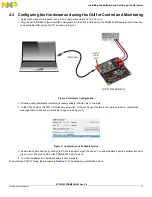
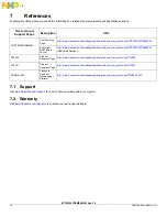
1. Apply input voltage to the board: use a 5.0 V supply connected to J2 (+) and J3 (-).
2. Plug the mini-USB side of the mini-USB to USB cable into the KL25Z USB port on the FRDM-KL25Z board and the other end
to an available USB port on the PC as shown in
Figure 8
.
Figure 8. Hardware Configuration
3. Windows will automatically install the necessary drivers. Wait for this to complete.
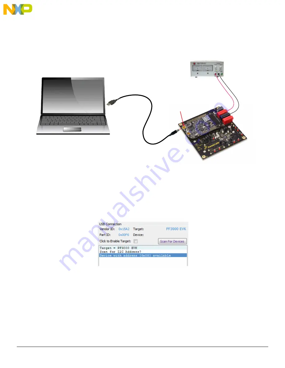
4. In the PF3000 GUI or PF3001 GUI window, click on the "Scan For Devices" button in the top-left portion. A confirmation
message that a valid device is available is logged (see
Figure 9
).
Figure 9. Confirmation of Available Device
5. Enable the communication by clicking the "Click to Enable Target" check box. You will immediately see the window turn from
grey to color. The green LED on the FRDM-KL25Z also turns on.
6. The GUI installation and hardware setup is now complete.
To emulate the PF3001, follow the procedure in
Section 5
for the hardware modification details.
(-)
(+)
KITPF3000FRDMEVM
KL25Z
USB
Port
USB Cable