NXP Semiconductors KIT34932SEKEVB Скачать руководство пользователя страница 1

Freescale Semiconductor, Inc.

User’s Guide

© Freescale Semiconductor, Inc., 2015. All rights reserved.

Document Number: KT34FS6407-34FS6408UG

Rev. 1.0, 8/2015

KIT34FS6407EVB and KIT34FS6408EVB 
Evaluation Board

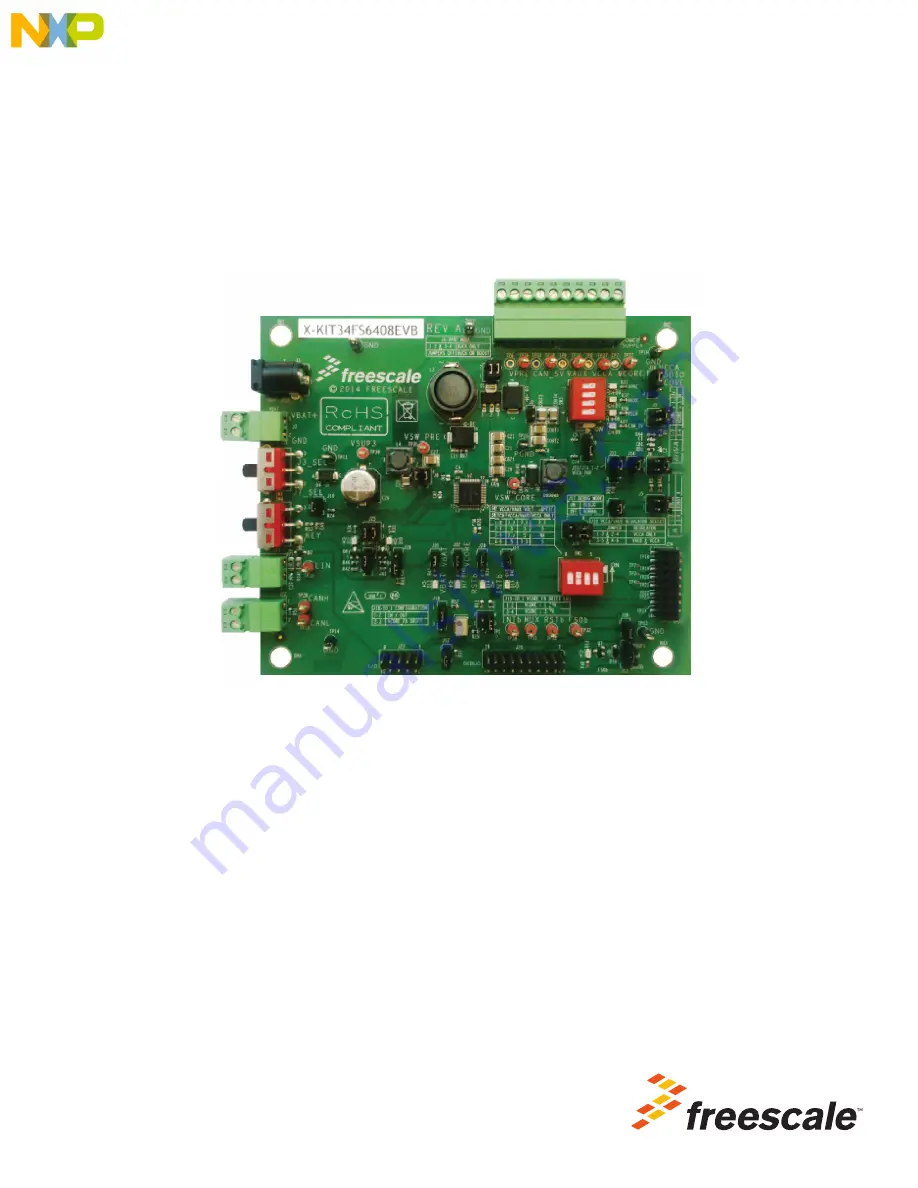
Figure 1. KIT34FS6407EVB and KIT34FS6408EVB Board

Содержание KIT34932SEKEVB

Страница 1: ...Inc User s Guide Freescale Semiconductor Inc 2015 All rights reserved Document Number KT34FS6407 34FS6408UG Rev 1 0 8 2015 KIT34FS6407EVB and KIT34FS6408EVB Evaluation Board Figure 1 KIT34FS6407EVB a...

Страница 2: ...1 Important Notice 3 2 Getting Started 4 3 Terms 5 4 Getting to Know the Hardware 6 5 Accessory Interface Board 21 6 Installing the Software and Setting up the Hardware 23 7 Initialization and Config...

Страница 3: ...w kit Freescale reserves the right to make changes without further notice to any products herein Freescale makes no warranty representation or guarantee regarding the suitability of its products for a...

Страница 4: ...link for your board KIT34FS6407EVB www freescale com KIT34FS6407EVB KIT34FS6408EVB www freescale com KIT34FS6408EVB Review your Tool Summary Page Look for Download documents software and other inform...

Страница 5: ...Fault Collection and Control Unit FS0B Fail safe Output Number 0 INTB Interrupt IO Input Output LDO Low dropout Regulator RSTB Reset SMPS Switching Mode Power Supply SPIGen Software utility installed...

Страница 6: ...g connector SPI bus CAN digital RSTB FS0B INTB Debug MUX_OUT Signalling LED to give state of signals or regulators 4 3 Device Features The MC34FS6407 and the MC34FS6408 are multi output ICs with power...

Страница 7: ...st Section VPRE DC DC selection mode either Boost or Buck Battery Connection Battery voltage input either on Jack black connector or Phoenix green connector Main Switch Battery voltage ON OFF Power Su...

Страница 8: ...ntial pair I Os of MC34FS6407_8 All IOs VDDIO and GND available Second Resistor Bridge VDRIFT Selection Bridge resistor for VCORE redundant check Main Signals of MC34FS6407_8 SPI VDDIO fail safe pin C...

Страница 9: ...to Know the Hardware KT34FS6407 34FS6408UG User s Guide Rev 1 0 8 2015 Freescale Semiconductor Inc 9 Figure 3 Default Board Configuration KIT34FS640XEVB REV A 2015 FREESCALE Switch Jumper Red LED Gre...

Страница 10: ...wer supply D8 VCCA Indicator of ADC power supply D9 CAN_5V Indicator of 5 0 V CAN voltage D10 IO_5 Indicator of IO_5 state D11 IO_4 Indicator of IO_4 state D12 FS0B Indicator for fail safe output numb...

Страница 11: ...RE Core voltage for the MCU TP28 CANH TP29 CANL TP30 LIN LIN bus Not available on KIT34FS640xEVB TP31 MUX_OUT Output from the analog multiplexer TP32 FS0B Fail safe output TP33 RSTB Reset signal TP34...

Страница 12: ...upply 8 GND Ground 9 VPRE Pre regulator voltage 10 PGND Power ground Table 6 Jumpers J1 through J31 Including Connectors Schematic Label Pin Number Pin Name Jumper Pin Function J1 Compensation network...

Страница 13: ...s power supply VSUP for VSUP1 and VSUP2 pins of MC34FS6407 or MC34FS6408 J9 Compensation network for FB_core part 2 1 2 VCORE 1 23 V 3 4 VCORE 3 3 V J10 VSNS_EN connects battery voltage before filter...

Страница 14: ...bles debug mode No jumper Normal mode 1 2 Debug mode J18 DRIFT_MONIT External resistor bridge monitoring 1 2 Second resistor bridge on IO_1 is disabled 2 3 Reserved for future use J19 VCCA VAUX regula...

Страница 15: ...to the MCU IO with an interrupt capability 13 RXD_L LIN receive pin connect to the MCU Not Available on KIT34FS640xEVB 14 TXD_L LIN transmit pin connect to the MCU Not Available on KIT34FS640xEVB 15...

Страница 16: ...pin2 TP18 pin3 TP2 pin4 TP19 pin5 TP3 pin6 TP20 pin7 TP4 pin8 TP21 pin9 SCLK SPI clock pin10 TP22 Not connected pin11 MOSI SPI Master Output Slave Input pin12 TP23 pin13 MISO SPI Master Input Slave Ou...

Страница 17: ...to LED D10 via transistor Q5 2 3 IO_5 pulled down J29 IO4_OUT IO_4 output configuration 1 2 IO_4 pulled down 2 3 IO_4 connected to LED D11 via transistor Q6 J30 Enable LED D12 for fail safe J31 Enabl...

Страница 18: ...CBx R1 C1 R2 C2 Figure 4 shows the compensation network Steady state voltage can be either 1 2 V or 3 3 V To tune the dynamic performance the board is equipped with two different bridges possible comb...

Страница 19: ...FS state machine is impacted Invoking this functionality involves both the board hardware and the software configuration On the hardware side the second resistor bridge must be configured by jumper J...

Страница 20: ...choice is possible at the same time 1 3 3 V 3 3 V 2 5 0 V 5 0 V 3 3 3 V 5 0 V This setting is not allowed if VAUX is not used option VCCA only selected by J19 4 5 0 V 3 3 V SW3 LEDs indicators for pow...

Страница 21: ...SB SPI and parallel ports built into Freescale s MC68HC908JW32 microcontroller The main function provided by this dongle is to allow Freescale evaluation kits that have a parallel port to communicate...

Страница 22: ...is configuration it is recommended that you use the EVB in a debug mode J17 configured as Debug In this mode there is no timeout used for the INIT phase so the initialization commands can be sent anyt...

Страница 23: ...a short cut an SPIGen icon appears on you desktop If you elected not to create a short cut the SPIGen executable is installed by default at C Program Files SPIGen 2 Download the configuration file MC3...

Страница 24: ...GLEVME Interface Dongle over and mount its IO Port connector to Connector J24 on the evaluation board 3 Connect a USB cable from the Interface Dongle to the PC 4 Set the EVB jumpers and switches as ne...

Страница 25: ...our desktop if you elected to create a short cut during the installation process Otherwise the icon resides in the folder C Program Files SPIGen The generic SPIGen start up screen appears 2 From the S...

Страница 26: ...e the reset error counter starts at level 1 and FS0B is asserted low To remove activation of FS0B the RST error counter must go back to value 0 seven consecutive good WD refresh decreases the reset er...

Страница 27: ...sers can also use MC3390X_GUI to modify the register table manually 1 To launch the MC3390X_GUI application click on the application icon located either on your desktop or in Program Files menu as sho...

Страница 28: ...the KIT3390xxEEVB button on the left side of the screen See Figure 13 Figure 13 MC3390X_GUI Configuration Selection 3 A screen similar to the one in Figure 14 appears showing the status of the registe...

Страница 29: ...Setting up the Hardware KT34FS6407 34FS6408UG User s Guide Rev 1 0 8 2015 Freescale Semiconductor Inc 29 4 In the right side of the GUI select NOT SAFETY and send the command as shown in Figure 15 Fig...

Страница 30: ...7 2 Normal Operation During normal operation after INIT phase both modes Normal and Debug allow you to send to send a WD refresh command In Debug mode no action is taken on a bad WD response In Norma...

Страница 31: ...5K TP13 C29 10uF J6 1 2 3 D12 RED A C C27 4 7uF TP24 D17 LED GRN A C J27 1 2 D14 RED A C TP26 C30 10nF RB1 200 J5 1 2 3 4 R52 510K J24 1 2 3 4 6 5 7 8 9 10 11 12 13 14 15 16 TP4 J14 1 2 R63 5 1K C48...

Страница 32: ...KT34FS6407 34FS6408UG User s Guide Rev 1 0 8 2015 32 Freescale Semiconductor Inc 9 Board Layout 9 1 Assembly Layer Top Figure 17 KIT34FS6407EVB KIT34FS6408EVB Assembly Layer Top KIT34FS640XEVB REV A 2...

Страница 33: ...Freescale Semiconductor Inc 33 9 2 Assembly Layer Bottom Figure 18 KIT34FS6407EVB KIT34FS6408EVB Assembly Layer Bottom NOTE This image is an exception to the standard top view mode of representation u...

Страница 34: ...1 CC21 10 F TDK CGA6M3X7R1C106K 3 10 1 C22 1 0 F TDK CGA5L3X7R1H105K160AB 11 2 C23 C33 4 7 F Murata GCM31CR71C475KA37 12 1 C24 0 22 F KEMET C0603C224K3RACTU 13 2 C27 C28 4 7 F Murata GCM32ER71H475KA55...

Страница 35: ...5 2 2 H EPCOS B82472G6222M000 Transistors 40 1 Q1 BUK9832 55A NXP Semiconductors BUK9832 55A 115 3 41 2 Q2 Q3 NJT4030P ON Semiconductor NJT4030PT3G 3 42 2 Q5 Q6 MMBF0201NLT1 G ON Semiconductor MMBF020...

Страница 36: ...P3S1M6QEA 70 2 SW2 SW3 SW_DIP 4_SM Grayhill 78RB04ST Test Points 71 12 TP2 TP3 TP4 TP5 TP18 TP19 TP20 TP21 TP22 TP23 TP24 TP25 TP_PTH NOT A COMPONENT NOT A COMPONENT 72 5 TP6 TP7 TP8 TP9 TP10 5006 Key...

Страница 37: ...KIT34FS6407EVB Tool Summary Page http www freescale com webapp sps site prod_summary jsp code KIT34FS6407EVB MC34FS6407 Product Summary Page http www freescale com webapp sps site prod_summary jsp co...

Страница 38: ...vision History KT34FS6407 34FS6408UG User s Guide Rev 1 0 8 2015 38 Freescale Semiconductor Inc 11 Revision History Revision Date Description of Changes 1 0 6 2015 Initial Release 8 2015 Corrected typ...

Страница 39: ...is provided solely to enable system and software implementers to use Freescale products There are no express or implied copyright licenses granted hereunder to design or fabricate any integrated circu...

Отзывы: