


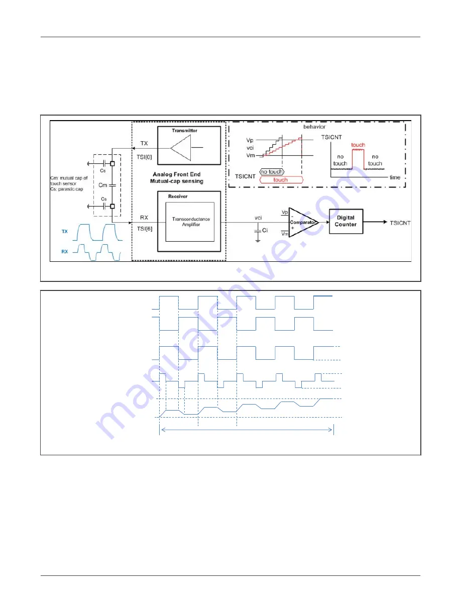
3.3 Mutual-cap sensing mode
Mutual-cap sensing includes transmitter and receiver. Under clocking, transmitter outputs pulses which decouple through mutual
cap then reach receiver site. Receiver amplifies the signal with noise cancellation method. The method is similar as charge transfer
circuit in self-cap sensing. That is, convert to averaging charge current on integration cap C
i
which creates step voltage V
ci
.
The step number of each scanning is accumulated to give final count TSICNT for each trigger.
Figure 17. Block diagram of TSI mutual-cap mode
ON
charge
Vp
Switching Clock: ph1
Vm
Single TSI Scan
0 STEP
1 STEP
N STEP
Comparator: Vci
Switching Clock: ph2
OFF
OFF
ON
discharge
Tx
Rx
charge discharge
V
pre
+
∆V
V
pre
-
∆V
V
DD5V
GND
Figure 18. Mutual capacitive mode timing
• V
pre
is selected by TSIx_MUL1[M_VPRE_CHOOSE].
• ΔV: signal voltage RX received, decided by VDD5V × C
m
/(C
m
+ C
s
).
• TX drive mode is controlled by TSIx_MUL1[M_MOD], -5 - +5 V is selected in
As shown in
, there are two phases controlled by the switching clock for the TSI mutual capacitive mode:
• Charge phase: The switch ph1 controls the charge phase, when ph1 turns on, the transmit channel outputs pulses which
are coupled through the mutual capacitance C
m
. Receiver converts the received voltage pulse (Vpre + ∆V) to the current
I
charge
through the resistor R
s
.
NXP Semiconductors
TSI Mutual-cap mode
KE17Z Dual TSI User Guide, Rev. 0, 05 May 2022
User Guide
20 / 37