


NXP Semiconductors
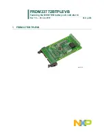
FRDM33772BTPLEVB
Featuring the MC33772B battery cell controller IC
FRDM33772BTPLEVBUG
All information provided in this document is subject to legal disclaimers.
© NXP B.V. 2018. All rights reserved.
User guide
Rev. 1.0 — 22 June 2018
12 / 17
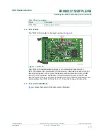
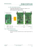
6.3 TPL communication connection
In a high-voltage Isolated application with a daisy chain configuration, up to 15
FRDM33772BTPLEVB boards may be connected.
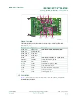
The TPL connections use the COMM (J4) connector.
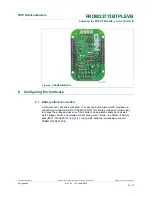
Figure 8. FRDM33772BTPLEVB board setup
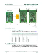
6.4 Fault chain connection
The FAULT chain connection is optional. When used, it connects through the FAULT (J3)
connector.