Getting to know the hardware
FRDM-HB2000-EVM evaluation board
, Rev. 1.0
NXP Semiconductors
7
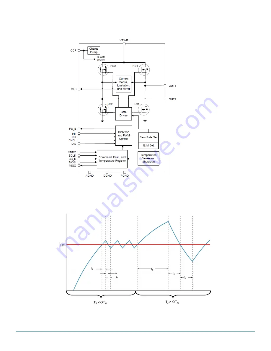
3.3.3 Architecture
Figure 4. Architecture
3.3.4 Thermal management
Figure 5. Architecture
Страница 1: ...NXP Semiconductors User s guide Document Number KTFRDMHB2000EVMUG Rev 1 0 3 2016 2016 NXP B V FRDM HB2000 EVM evaluation board Figure 1 FRDM HB2000 EVM...
Страница 2: ...e 3 2 Getting started 4 3 Getting to know the hardware 5 4 FRDM KL25Z Freedom SPI dongle 14 5 Installing the software and setting up the hardware 18 6 Schematic 25 7 Board layout 26 8 Board bill of ma...
Страница 3: ...icated in the kit it may be returned within 30 days from the date of delivery and will be replaced by a new kit NXP reserves the right to make changes without further notice to any products herein NXP...
Страница 4: ...ments software and other information Once the files are downloaded review the user guide in the bundle The user guide includes setup instructions BOM and schematics Jump start bundles are available on...
Страница 5: ...ard features the following Built in reverse battery protection Test points allows probing its signals Built in voltage regulator to supply logic level circuitry LEDs to indicate the supply status and...
Страница 6: ...d Eight selectable slew rates via the SPI 0 25 V s to more than 16 V s for EMI and thermal performance optimization Four selectable current limits via the SPI 5 4 7 0 8 8 10 7 A covering a wide range...
Страница 7: ...Getting to know the hardware FRDM HB2000 EVM evaluation board Rev 1 0 NXP Semiconductors 7 3 3 3 Architecture Figure 4 Architecture 3 3 4 Thermal management Figure 5 Architecture...
Страница 8: ...egulator 5 0 V regulator for VDD and supply Jumpers Jumpers for configuring the board for different modes of operation Reverse Battery Protection MOSFET for protecting MC33HB2000 in reverse battery co...
Страница 9: ...Figure 7 LED locations Table 3 LED display LED ID Description VBAT GREEN LED indicates when main battery supply is connected VDD GREEN LED indicates when 5 0 V supply is connected FS_B RED LED illumi...
Страница 10: ...IN2 control through MCU parallel output on J10 Pin 3 DATA1 2 3 IN2 control through external input on J15 Pin 2 J4 CS_B 1 2 CS_B control through MCU SPI output J10 Pin 6 SPI_CS_B 2 3 CS_B pulled up to...
Страница 11: ...ntrol of the load 3 9 Test point definitions The following test points provide access to various signals to and from the board J17 VDD 1 2 VDD supply from regulator U2 2 3 VDD supply from FRDM board J...
Страница 12: ...ts IN_1 IN1 Direction control in H Bridge mode and OUT1 control in half bridge mode IN_2 IN2 PWM control in H Bridge mode and OUT2 control in half bridge mode VPWR VPWR System voltage VDDQ1 VDDQ VDDQ...
Страница 13: ...minal connections The board has the following screw terminal connections to connect the power supply and the load Figure 10 Screw terminal locations Table 8 Screw terminal connections Screw Terminal N...
Страница 14: ...was chosen specifically to work with the FRDM HB2000 EVM kit because of its low cost and features The FRDM KL25Z board makes use of the USB built in LEDs and I O ports available with NXP s Kinetis KL...
Страница 15: ...DM KL25Z Freedom SPI dongle FRDM HB2000 EVM evaluation board Rev 1 0 NXP Semiconductors 15 Figure 12 Connecting the FRDM HB2000 EVM to the FRDM KL25Z Figure 13 FRDM KL25Z to FRDM HB2000 EVM connection...
Страница 16: ...TC8 No connection J24 15 J1 15 N C PTC11 Not connection J24 16 J1 16 N C PTC9 No connection J10 1 J2 1 DATA0 IN1 PTC12 IN1 signal for the H Bridge J10 2 J2 2 N C PTA13 No connection J10 3 J2 3 DATA1 I...
Страница 17: ...nnection J25 1 J9 1 N C PTB8 No connection J25 2 J9 2 N C SDA_PTD5 No connection J25 3 J9 3 N C PTB9 No connection J25 4 J9 4 N C P3V3 No connection J25 5 J9 5 N C PTB10 No connection J25 6 J9 6 N C R...
Страница 18: ...oard 5 1 1 Step by step instructions for setting up the hardware for use with a FRDM KL25Z To configure the FRDM HB2000 EVM for use with the FRDM KL25Z do the following 1 Connect the FRDM HB2000 EVM t...
Страница 19: ...3HB2000 datasheet to configure the board for use in a specific environment 1 Connect the function generator to the EX_IN jumper with one channel attached to each pin 2 Change the board jumper connecti...
Страница 20: ...SPIGen wizard to create a short cut a SPIGen icon appears on the desktop If elected not to create a short cut the SPIGen executable is installed by default at C Program Files SPIGen Note Installing t...
Страница 21: ...ware and setting up the hardware FRDM HB2000 EVM evaluation board Rev 1 0 NXP Semiconductors 21 Figure 17 MC33HB2000 SPI window 6 Reading all the SPI registers displays the following default status Fi...
Страница 22: ...top of each register to read the content of each register Write Click individual bits of any register and then press the corresponding write button to write into the register SPI control This section...
Страница 23: ...valid for Half Bridge mode ENBL Yes ENBL is logic HIGH the H Bridge is operational No ENBL is logic LOW the H Bridge outputs are tri stated and placed in sleep mode DIS DIS is logic HIGH both OUT1 and...
Страница 24: ...and frequency 2 Reverse High side recirculation IN1 PWM signal with selected duty cycle and frequency IN2 1 3 Forward Low side recirculation IN1 PWM signal with selected duty cycle and frequency IN2...
Страница 25: ...OUT1 OUT2 VDD VDDQ EX_IN1 EX_IN2 CFB_READ FRDM_VDD VDD FRDM_VDD CFB_READ CFB DIS VDD_REG CCP CFB_READ FS_B R2 47K J25 HDR_2X8 1 2 3 4 6 5 7 8 9 10 11 12 13 14 15 16 FWD GREEN A C FS_B_ HDR_1X2 1 2 J20...
Страница 26: ...Board layout FRDM HB2000 EVM evaluation board Rev 1 0 26 NXP Semiconductors 7 Board layout 7 1 Silkscreen...
Страница 27: ...70 107F Capacitors 8 2 C1 C3 0 1 F CAP CER 0 1 F 50 V 10 X7R 0805 C0805C104K5RAC 9 1 C2 100 F CAP ALEL 100 F 50 V 20 AEC Q200 RADIAL SMT MAL214699104E3 10 2 C4 C5 0 033 F CAP CER 0 033 F 50 V 10 X7R 0...
Страница 28: ...2 15 29 1 Q3 TRAN NPN DRIVER 500 mA 80 V AEC Q101 SOT23 SMMBTA06LT1G Notes 1 NXP does not assume liability endorse or warrant components from external manufacturers are referenced in circuit drawings...
Страница 29: ...com support for a list of phone numbers within your region 10 2 Warranty Visit www nxp com warranty to submit a request for tool warranty NXP com support pages Description URL FRDM HB2000 EVM Tool Sum...
Страница 30: ...Revision history FRDM HB2000 EVM evaluation board Rev 1 0 30 NXP Semiconductors 11 Revision history Revision Date Description of Changes 1 0 3 2016 Initial release...
Страница 31: ...damages Typical parameters that may be provided in NXP data sheets and or specifications can and do vary in different applications and actual performance may vary over time All operating parameters i...
Страница 32: ...Mouser Electronics Authorized Distributor Click to View Pricing Inventory Delivery Lifecycle Information NXP FRDM HB2000 EVM...