5
Establishing polarity.
It is very important
that left and right connections be made with
the same plus/minus polarity.
•
Most speaker wire is polarity coded. This
means that each conductor is labeled either
“+” positive or “–” negative. The (+) posi-
tive conductor may be a different color or
texture than the (–) negative conductor. For
example, it may be copper-colored (instead
of silver-colored), have a white stripe print-
ed on it, have a series of fine ridges
stamped in it or simply be labeled with little
“+” marks.
•
NX-PROSUB125/NX-PROSUB300 FROM
RECEIVER terminals are color-coded: Red
for positive (+) and black for negative (–).
•
Any connection that uses speaker wire
requires care in maintaining polarity. When
connecting speakers or a subwoofer to
speaker terminals, or during NX-PRO-
SUB125/ NX-PROSUB300
Method A
Hookup,
make sure to connect “+” wires to
“+” terminals, and “–” wires to “–” termi-
nals. For example, if your speaker wire has
one copper-colored conductor and one sil-
ver-colored conductor, connect both ends of
the copper-colored wire (+) to red (+) ter-
minals. Likewise, connect the wire you’ve
identified as negative (in this case, the sil-
ver-colored wire), to black (–) terminals.
Preparing speaker wire
1.
Separate the two conductors that make
up each wire for a distance of about one
inch. Then strip off
1
/
2
˝ of insulation
from both ends of each con-
ductor using a wire stripper,
diagonal pliers or knife.
2
. Twist each set of thin wires into
a tightly bunched spiral. If your
wire is exceptionally thick (12-
gauge zipcord or special speaker
interconnect cable), divide the
strands into three equal bundles and
twist each into a spiral.
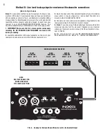
FIG. 3 - Hookup for Receivers and Integrated Amplifiers
without a Subwoofer Output
RECEIVER OR INTEGRATED AMPLIFIER
FRONT
SPEAKERS
LEFT RIGHT
COLOR
TOP
SHAFT
STRIPPED
END (
1
/
2
˝)
WIRE
To connect wire:
1. Unscrew (counter- clockwise) the top
(color portion)
2. Place the stripped metal wire in the hole
in the metal shaft
3. Tighten (clockwise) the top (color portion)
back down on wire (make sure wire
insulation is not under the plastic nut).
FRONT LEFT
SPEAKER
FRONT RIGHT
SPEAKER
NX-PROSUB125 &
NX-PROSUB300
Speaker Wire
Connection Detail
loosen
tighten
(Refer to Fig. 3 above)
1. IMPORTANT: Make sure that ALL stereo system components
including the NX-PROSUB125/NX-PROSUB300 are turned OFF
before proceeding.
2.
Following the prior instructions on this page, strip and twist
TWO lengths of speaker wire that will reach between your receiver’s
left and right speakers terminals and the NX-PROSUB125/NX-PRO-
SUB300. Make these two lengths of wire only as long as is neces-
sary to run between the two components.
3.
Connect one speaker wire to the RIGHT “+” and “–” speaker
terminals of your receiver or integrated amplifier. Then connect the
other end of this speaker wire to the RIGHT “+” and “–” FROM
RECEIVER terminals on the back of the NX-PROSUB125/NX-PRO-
SUB300. Use the tips on determining speaker wire polarity to make
sure that “+” is connected to “+” and “–” is connected to “–”.
4.
Connect the other speaker wire to the LEFT “+” and “–” speaker
terminals of your receiver or integrated amplifier. Then connect the
other end of this speaker wire to the LEFT “+” and “–” FROM
RECEIVER terminals on the back of the NX-PROSUB125/NX-PRO-
SUB300. As in step 3, double check “+” and “–” polarity.
5.
Connect your main/satellite speakers to your receiver as shown in
Fig. 3.
6.
You are now ready to put your NX-PROSUB125/NX-PROSUB-
300 subwoofer into use. Skip to “E – INITIAL LISTENING TEST.”
Method A:
Amplifier wiring hookup steps for receivers or surround sound receivers with NO sub output jack


