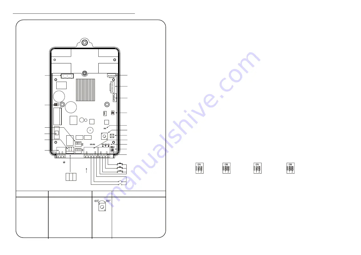
7. Controller Explanations and Instructions
Wire Diagram
Motor Interface
220V/110V
Switch Jumper
Cap 1
UP/DOWN Limit
Signal Output
Interface and
Indicators
Fuse
R & G L i g h t
Interface
P o w e r I n p u t
Interface
MotorEncoder
Interface
MotorSensorIn
terface
RemoteControll
erInterface
DIP Switch 2
Function Indicator
Boom Up Angle Adjustment
Knob
SET
+-
DC
12
V
<
0
.
2
A
L
N
Signal Input Indicator
Photocell and Loop Detector
Interface
J1 DIP Switch 1 and Jumper 1
Wire Control Interface
STOP
DOWN
UP
COM
COM Interface
Loop Detector Signal Input
Photocell Signal Input
P
h
o
to
c
e
ll P
o
w
e
r
R
e
d L
ig
h
t
G
re
e
n L
ig
h
t
C
O
M
DIP Switch Setting
DIP Switch 1: Speed setting
ON/ON: 3S; OFF/ON: 4S;
ON/OFF: 5S; OFF/OFF: High
intensity of auto-reversing
DIP Switch 2:
DIP 1: Signal type
O F F : N o r m a l O p e n , O N :
Normal Close
DIP 2: Learning mode after
power-on
OFF: Boom up and down; ON:
Boom up only
Jumper 1: Auto-aging test
Left: close; Right: open.
Delay Auto-closing Setting
Pressing and holding SET button then power on,
if the Function Indicator constant lighting means
delay auto-closing function is of f if twinkling,
the twinkling times is the seconds of the delay
auto-closing.
Opening method: Press UP button (of the remote
controller) to open this function, after open, the
delay auto-closing time is 3 seconds, each
pressing of the UP button increases by 1 second,
the max is 60 seconds.
Closing method: Press S TO P button, the
Function Indicator constant lighting means close.
Read seconds: Press DOWN button, the Function
Indicator twinkling times is the seconds of the
delay auto-closing.
Release the SET button to save and start
working.
Boom Up Angle
Setting
Counterclockwise
to the end is 60
°
Clockwise to the
end is 90
°
Middle is end is
60
°
~85
°
Horizontal and vertical fine adjustment
Horizontal adjustment: In UP limit status, pressing
and holding SET button, then press UP button (of the
remote controller) (if angle over 90
°
) or DOWN
button (if angle less than 90
°
) to adjust the value
(0~25). Release the SET button, the adjustment is
done when the boom open to the UP limit status next
time.
Vertical adjustment: In DOWN limit status, pressing
and holding SET button, then press OPEN button (of
the remote controller) (if angle less than 0
°
) or
DOWN button (if angle over 0
°
) to adjust the value
(0~40). Release the SET button, the adjustment is
done when the boom close to the DOWN limit status
next time.
Note: During adjusting, when press STOP button, the
twinkling times of the Function Indicator means the
current adjusted value.
7.1. Controller interface explanations
All the electrical connections are done before delivery. The necessity is to
connect the power and grounding connection. Explanations and instructions
for the main function interfaces and indicator light is as following:
7.1.1. 220V/110V switch jumper cap:
This barrier motor and controller support AC220V/110V power input, the
jumper cap is plugged in before delivery, if need to change the input voltage,
please plug the jumper cap into correct position before power on (plug on the
left is 220V, plug on the right is 110V).
7.1.2. R&G light interface:
This function is no power, same as switch, MCOM ” need to connect with
corresponding power of the R&G light. When boom falling down to
horizontal position, red light will keep lighting; when boom lifting up to
vertical position, green light will keep lighting. During the boom falling down
or lifting up, the red light will keep lighting. (Please refer to Appendix II for
wire diagram)
7.1.3. Wire control signal input interface:
This interface is dry contact input signal, UP/ DOWN / STOP connect with
MCOM ”, the control board will respond accordingly. User can use this
interface to connect with parking system, and it can also connect button
switch to control the barrier. (Please refer to Appendix III for drive
requirement for main control board wire control)
7.1.4. Photocell and loop detector interface:
This interface is dry contact input signal, only for responding opening when
shorts circuit MPhotocell” and“ COMH during closing, responding closing
when shorts circuit “ LoopHand MCOMH if opening to up limit position,
responding opening when shorts circuit “ LoopHand MCOMH during
3S
4S
5S
Hig h intensity of
auto-reversing
7.1.7. Jumper 1:
This Jumper is for closing (insert left) or opening (insert right) auto-
aging test function; Opening this function can realize barrier gate auto-
open, close, and open during closing process for auto-aging test.
7.1.8. DIP Switch 2:
DIP 1 for setting signal input type, means the wire signal input type of
“STOPH, MLOOP DETECTOR” and “PHOTOCELL”. DIP set to be
OFF, means the barrier responses action when short circuited signal interface
and COM interface; DIP set to be ON, means the barrier responses action
when disconnected signal interface and COM interface.
DIP 2 for learning mode after power-on: set to be OFF, means the
barrier will open and close slowly one time after power-on; set to be
6
.
.
7
.
.


