Nvidia MCP79 ION Скачать руководство пользователя страница 21

content might be changed due different version,pls follow the content what showed. 


PDF created with pdfFactory Pro trial version 

www.pdffactory.com

 Mainboard

MCP79/7A

BIOS Setup

This chapter provides basic information on the BIOS Setup program and allows you to
configure the system for optimum use. You may need to run the Setup program when:

* An error message appears on the screen during the system booting up, and requests

you to run BIOS SETUP.

* You want to change the default settings for customized features.

Entering Setup

Power on the computer and the system will start POST (Power On Self Test) process.
W hen the m essage below appears on the screen, press <DEL> key to enter Setup.

Press DEL to enter SETUP

If the message disappears before you respond and you still wish to enter Setup, restart
the system by turning it OFF and On or pressing the RESET button. You may also restart
the system by simultaneously pressing <Ctrl>, <Alt>, and <Delete> keys.

Getting Help

After entering the Setup m enu, the first menu you will see is the Main Menu.

Main Menu

The main m enu lists the setup functions you can m ake changes to. You can use the
arrow keys  (

↑↓

) to select the item . The on-line description of the highlighted setup

function is displayed at the bottom of the screen.

Sub-Menu

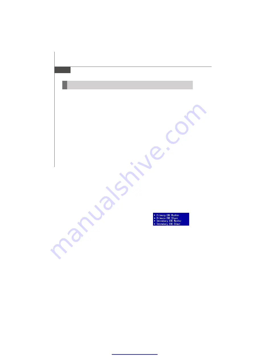
If you find a right pointer symbol (as shown in the right view)
appears to the left of certain fields that means a sub-menu
containing additional opt ions can be launched from t his
field. You can use control keys  (

↑↓

) to highlight the field

and press <Enter> to call up the sub-menu. Then you can
use the control keys to enter values and move from field to field within a sub-menu. If
you want to return to the main menu, just press <Esc >.

General Help <F1>

The BIOS setup program provides a General    Help screen. You can call up this screen
from any menu by simply pressing <F1>. The Help screen lists the appropriate keys to
use and the possible selections for the highlighted item. Press <Esc> to exit the Help
screen.

3-2

*

Содержание MCP79 ION

Страница 1: ...ter 2 Hardware Setup 2 1 2 2 Memory 2 2 Power Supply 2 3 Back Panel I O Connector Jumper Slot Chapter 3 BIOS Setup 3 1 BIOS Setup 3 2 Software Information 3 5 PDF created with pdfFactory Pro trial ver...

Страница 2: ...tem efficiency the Nvidia MCP79 Ion Series accommodate the latest Intel AtomTM processor N270 230 330 and support two DDR2 533 667 800 DDR2 DIMM slot to provide the maximum of 4GB memory capacity Thre...

Страница 3: ...LAN Supports 100 1000M by RTL8103EL or 8111DL Controller Audio ALC662 5 1 channel compliant with Azalia 1 0 specs IDE 1 Mini IDE port Supports Ultra DMA 66 100 mode Supports PIO Bus Master operation m...

Страница 4: ...nector 4 serial port connectors 1 ESATA port connector 1 CD_IN pinheader 1 HDMI_SPDIF pinheader 1 Com2 mode jumper 1 ESATA connector 1 LCD power connector 1 VGA pinheader 1 COM1_PW pinheader 5 COM por...

Страница 5: ...ntal Storage Environment Temperature 20oC 80oC Humidity 5 90 non condensing Operation Environment Temperature 0oC 60oC Humidity 5 90 non condensing PDF created with pdfFactory Pro trial version www pd...

Страница 6: ...Key Board RCA 2 USB Ports 2 USB Ports 2 USB Ports Fiber HDMI DVI ESATA LAN VGA Port PCI F PANEL MINI I DE 4XSATA ESATA LVDS ATXPower SYS FAN 2XDDR2 LPT F USB 4 COM Ports CPU FAN IRDA Nvidia MCP79 ION...

Страница 7: ...PDF created with pdfFactory Pro trial version www pdffactory com MCP79 7A ION Series Mini ITX Mainboard Back Mainboard MCP79 7A MINI PCIE 1 6...

Страница 8: ...e careful in holding the components and follow the installation procedures For some components if you install in the wrong orientation the components will not work properly Use a grounded wrist strap...

Страница 9: ...19 5V 20 5V PIN SIGNAL 1 3 3V 2 3 3V 3 GND 4 5V 5 GND 6 5V 7 GND 8 PWROK 9 5VSB 10 12V Pin Definition ATX 10 1 20 11 PDF created with pdfFactory Pro trial version www pdffactory com Memory The DIMM s...

Страница 10: ...lugged in as required Providing an external hot swap pable drive solution similar to USB SATA offers much higher speeds than the USB bus SPDIF Port Fiber RCA Sony Philips Digital InterFace A serial in...

Страница 11: ...cable to it SpeedIndicator ActivityIndicator Left LED Right LED Active LED 100M 1000MSpeedLED LED Color Yellow Green Orange 10M Cable Plug in No Transmission Slow Blinking OFF Transition SwiftlyBlinki...

Страница 12: ...tor is a high speed Serial ATA interface port Each connector can con nect to one Serial ATA device SATA4 SATA1 SATA2 SATA3 Important If you install two IDE devices on the same cable you must configure...

Страница 13: ...to take advantage of the CPU fan control CPUFAN SENSOR 12V GND Front USB Pinheader This pinheader compliant with Intel I O Connectivity Design Guide is ideal for con necting high speed USB interface p...

Страница 14: ...connector is provided for LCD backlight options 1 PIN SIGNAL 1 12V 2 GND 3 InverterOn 4 BacklightControl 5 5V Pin Definition VGA Connector VGA CON 1 3 DATA 5 CLK 7 GND 9 Pin Definition KB Connector K...

Страница 15: ...Pin Definition Parallel Port Header LPT1 The mainboard provides a 26 pin header for connection to an optional parallel port bracket The parallel port is a standard printer port that supports Enhanced...

Страница 16: ...Design Guide 1 2 9 10 F PANEL HDD LED Reset Switch Power LED Power Switch Front Panel Audio Connector F AUDIO This connector allows you to connect the front panel audio and is compliant with Intel Fr...

Страница 17: ...or MCP79 ION Only The LVDS Low Voltage Differential Signal connector provides a digital interface typically used with flat panels After connecting an LVDS interfaced flat panel to the JLVDS1 be sure t...

Страница 18: ...6 2 5 1 6 12V 2 5 1 6 2 5 1 6 2 5 5V 3 3V Inverter Power umper INVERTER PWR INVERTER PWR J 1 6 2 5 1 6 12V 2 5 1 6 2 5 1 6 2 5 5V 3 3V COM Port Power Jumper COM1 PW COM1 PW 1 6 2 5 1 6 12V 2 5 1 6 2...

Страница 19: ...ion for the expansion card to configure any necessary hardware or software settings for the expan sion card such as jumpers switches or BIOS configuration PCI Peripheral Component Interconnect Express...

Страница 20: ...provides information on the BIOS Setup program and allows you to configure the system for optimum use You may need to run the Setup program when An error message appears on the screen during the syst...

Страница 21: ...he system by simultaneously pressing Ctrl Alt and Delete keys Getting Help After entering the Setup menu the first menu you will see is the Main Menu Main Menu The main menu lists the setup functions...

Страница 22: ...u to specify your settings for fequency voltage control and overclocking Load Fail Safe Defaults Use this menu to load the default values set by the BIOS vendor for stable system performance Load Opti...

Страница 23: ...t settings for optimal system performance 2 Setup Date Time Select the Standard CMOS Features and press Enter to enter the Standard CMOS Features menu Adjust the Date Time fields 3 Save Exit Setup Use...

Страница 24: ...y and follow the pop up screen to complete the installation The Driver Utility CD con tains the Driver menu The Driver menu shows the available drivers Install the driver by your desire and to activat...

Отзывы: