background image

4  |  nVent.com

9 Volt

battery

Menu

Down

Up

Next

7A

8

Ø
Ø

GFCB

7B

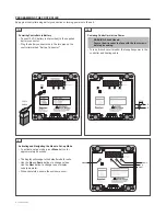
Powering Controller via Battery

•  Connect 9 VDC battery (not provided) to the supplied 

battery connector.

•  Plug the battery connector onto the two pins on the 

controller marked “Battery Connector.”

Reprogram controller using battery connection or turning power onto the unit.

Activating and Navigating the Menu in Set-up Mode

•  To activate set-up mode, press Menu button for 

approximately 5 seconds.

•  The display will change to the default mode for units.
•  Use the Up and Down buttons to change values. 

Use the Next button to change to next display 

code/parameter.

•  When completed, secure the enclosure cover.

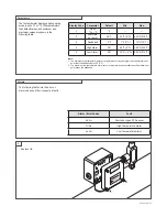
Powering Controller via Line Power

•  Turn on branch circuit breaker that supplies power to the 

controller and heating cable.

  WARNING: Shock Hazard.


Secure the wire cover in place with the four screws 

before proceeding.

PROGRAMMING THE CONTROLLER

Содержание JBS-100-EC

Страница 1: ...specified parts only Do not use substitute parts or vinyl electrical tape The black heating cable core and fibers are conductive and can short They must be properly insulated and kept dry Damaged bus wires can overheat or short Do not break bus wire strands when scoring the jacket or core Keep components and heating cable ends dry before and during installation Use only fire resistant insulation m...

Страница 2: ... You can then use this diagram for reference when rewiring Disconnect all wires Remove the screws and the PC board Note You may need to loosen or remove external fittings on the box to get the PC board out Install the new PC board using the four copper screws Note Once installed tighten any external fittings WARNING Shock Hazard Before you begin dismantling your controller turn OFF THE power and l...

Страница 3: ...r MI heating cable RTD Heating cable ground GLCB Phase A Phase B Ground Pipe Mounted Enclosures JBS 100 ECP A Wall Mounted Enclosures JBS 100 ECW A Incoming Power GLCB Phase A Phase B Alarm Ground MI heating cable using direct connection RTD MI heating cable Power Terminal Block RTD Input Optional Alarm Contacts 5 6 Reconnect all wiring Use the wiring diagrams below for reference Replace wire cove...

Страница 4: ...avigating the Menu in Set up Mode To activate set up mode press Menu button for approximately 5 seconds The display will change to the default mode for units Use the Up and Down buttons to change values Use the Next button to change to next display code parameter When completed secure the enclosure cover Powering Controller via Line Power Turn on branch circuit breaker that supplies power to the c...

Страница 5: ...m set point must always be larger than the maintain set point plus the deadband plus 5 F 3 C 2 The maximum low temperature alarm set point must always be smaller than the maintain set point minus the deadband Display Code Parameter Default Min Max 1 Units F or C F 2 Maintain set point 40 F 32 F 0 C 425 F 218 C 3 Deadband 5 F 1 F 1 C 10 F 10 C 4 High Alarm 1 Off 38 F 3 C 482 F 250 C 5 Low Alarm 2 O...

Страница 6: ...specifications without notice Raychem IM H57564 JBS100EC EN 1805 PN P000000302 nVent com North America Tel 1 800 545 6258 Fax 1 800 527 5703 thermal info nvent com Europe Middle East Africa Tel 32 16 213 511 Fax 32 16 213 604 thermal info nvent com Asia Pacific Tel 86 21 2412 1688 Fax 86 21 5426 3167 cn thermal info nvent com Latin America Tel 1 713 868 4800 Fax 1 713 868 2333 thermal info nvent c...

Отзывы: