


NuMaker-M2351SF
Sep.
24, 2019
Page
19
of 35
Rev 1.00
N
UMA
K
E
R
-M2
35
1
S
F
U
S
E
R MA
NUA
L
Ma
k
er Nu
-m
be
d
NUC
47
2
Us
er Man
ua
l
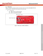
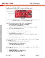
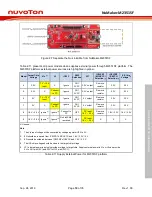
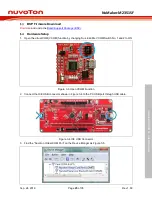
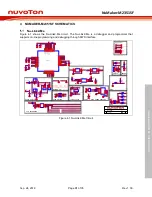
Figure 2-7 Separate the Nu-Link2-Me from NuMaker-M2351SF
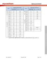
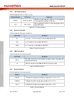
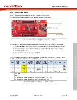
Table 2-11 presents all power models when supplies external power through M2351SF platform. The
M2351SF platform external power sources are highlighted in yellow.
Model
Target Chip
Voltage
Vin
[1]
J2
ICEJ3
SW2
Selection
JP1
ICEJPR1
(MCUVCC)
Selection
[2]
ICEJPR2
(ICEVCC)
Selection
[3]
ICE Chip
Voltage
[4]
4
3.3 V
7 V ~ 12 V
Input
X
Ignore
NU1
3VCC
3.3 V output
Remove
resistor
3.3 V
3.3 V
5
3.3 V
X
Connect
to PC
Ignore
NU1
3VCC
3.3 V output
Remove
resistor
3.3 V
3.3 V
6
5 V
7 V ~ 12 V
Input
X
Ignore
NU1
5VCC
5 V output
Remove
resistor
3.3 V
3.3 V
7
5 V
X
Connect
to PC
Ignore
NU1
5VCC
5 V output
Remove
resistor
3.3 V
3.3 V
8
1.8 V ~ 3.6 V Ignore
[5]
Ignore
[5]
Connect to
PC
OFF
DC Input
1.8 V ~ 3.6 V
Remove
resistor
1.8 V / 3.3 V 1.8 V / 3.3 V
9
1.8 V ~ 3.6 V Ignore
[5]
Ignore
[5]
Nu-Link2-Me
removed
OFF
DC Input
1.8 V ~ 3.6 V
X
X
X
X: Unused.
Note
:
1.
The Vin input voltage will be converted by voltage regulator UP2 to 5 V.
2.
0Ω should be removed from ICEJPR1’s MCUVCC and 1.8 V / 3.3 V / 5 V.
3.
0Ω should be soldered between ICEJPR2’s ICEVCC and 1.8 V / 3.3 V.
4.
The ICE chip voltage should be close to the target chip voltage.
5.
JP1 external power input only provides voltage to target chip. Supply external power to Vin or J2 can provide
5V to NU1 pin5 (5V) and 3.3V to NU1 pin4 (3VCC).
Table 2-11 Supply External Power for M2351SF platform


