ISD94100 Series Technical Reference Manual
Sep 9, 2019
Page
767
of 928
Rev1.09
IS
D
9
410
0
S
ER
IE
S
T
E
C
HN
ICA
L
RE
F
E
RE
NCE
M
AN
U
AL
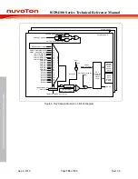
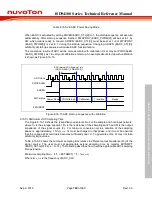
Figure 6.16-12 ADC Extend Sampling Timing Diagram
6.16.5.11 Conversion Result Monitor by Compare Mode
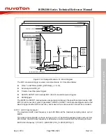
The ADC controller provides four sets of compare registers EADC_CMP0 ~ EADC_CMP3 to
monitor a maximum of four specified sample module 0~12 conversion results from ADC conversion
module, as shown in the Figure 6.16-13. User can select which sample module result to be
monitored by set CMPSPL (EADC_CMPn[7:3], n =0~3) and CMPCOND (EADC_CMPn[2], n =0~3)
is used to check conversion result is less than specify value or greater than (equal to) value
specified in CMPDAT (EADC_CMPn[27:16] , n =0~3). When the conversion of the sample module
specified by CMPSPL (EADC_CMPn[7:3], n =0~3) is completed, the comparing action will be
triggered one time automatically. When the compare result meets the compare condition, the
internal compare match counter will increase 1. If the compare result does not meet the condition,
the compare match counter will reset to 0. When counter value reach the setting of (CMPMCNT
(EADC_CMPn[11:8])+1, n =0~3) then ADCMPFn (EADC_STATUS2[7:4], n =0~3) bit will be set to
1, if ADCMPIE (EADC_CMPn[1] , n =0~3) is set then an ADINT3 interrupt request is generated.
User can use it to monitor the external analog input pin voltage transition. Detailed logics diagram
is shown in Figure 6.16-13.
Sample module
0~12
DAT Result Register
RESULT >= CMPDAT
RESULT < CMPDAT
CMPCOND(EADC_MPPn[2])
1
0
APCMPFn
(EADC_STATUS2[7:4])
Control Logic
Match
Counter
CMPMCNT
(EADC_CMPn[11:8])
CMPSPL(EADC_CMPn[7:3])
RESULT
(EADC_DATn[11:0]
CMPDAT(EADC_CMPn[27:16])
Note:
CMPDAT (EADC_CMPn[27:16]
RESULT(EADC_PATn[11:0]
+
-
12-bit Digital Comparator
ADCMPOn
(EADC_STATUS2[15:12])
Figure 6.16-13 ADC Conversion Result Monitor Logics Diagram
The ADC controller supports a window compare mode. User can set CMPWEN (EADC_CMP0[15]/
EADC_CMP2[15] ) to enable this function. If user enable this function, ADCMPF0
(EADC_STATUS2[4]) will be set when both EADC_CMP0 and EADC_CMP1 compared condition
matched. ADCMPF2 (EADC_STATUS2[6]) will be set when both EADC_CMP2 and EADC_CMP3
compared condition matched.
6.16.5.12 Double Buffer Mode
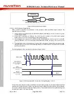
The ADC controller supports a double buffer mode in sample module 0~3. If user enable DBMEN
(EADC_SCTLn[23], n=0~3), the double buffer mode will enable. In double buffer mode, after first
time ADC convert finish, the VALID (EADC_DATn[17], n=0~3) will set to high, but VALID
(EADC_DDATn[17], n=0~3) will keep low. And the second time ADC converts finish, VALID
(EADC_DDATn[17],n=0~3) will set to high either, Then, user can get the ADC results from
EADC_DATn and EADC_DDATn register.
6.16.5.13 PDMA request
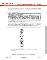
The ADC controller supports PDMA. User can enable PDMAEN (EADC_CTL[11]) and configure
PDMA channel’s source address as EADC_CURDAT (0x4C). After enable PDMAEN
and PDMA channel enable, if any VALID (EADC_DATn[17],n=0~12) is high, ADC controller will
send request to PDMA and PDMA will read EADC_CURDAT to get result. The EADC_CURDAT
Содержание ISD94100 Series
Страница 528: ...ISD94100 Series Technical Reference Manual Sep 9 2019 Page 528 of 928 Rev1 09 ISD94100 SERIES TECHNICAL REFERENCE MANUAL...
Страница 626: ...ISD94100 Series Technical Reference Manual Sep 9 2019 Page 626 of 928 Rev1 09 ISD94100 SERIES TECHNICAL REFERENCE MANUAL...
Страница 702: ...ISD94100 Series Technical Reference Manual Sep 9 2019 Page 702 of 928 Rev1 09 ISD94100 SERIES TECHNICAL REFERENCE MANUAL...
Страница 875: ...ISD94100 Series Technical Reference Manual Sep 9 2019 Page 875 of 928 Rev1 09 ISD94100 SERIES TECHNICAL REFERENCE MANUAL...

