background image


18 


  SECTION 6 


 DIAGRAMS AND DRAWINGS 


Содержание OT 020

Страница 1: ...NÜVE SANAYİ MALZEMELERİ İMALAT VE TİCARET A Ş BENCH TOP STEAM STERILIZERS OT 020 OT 020V SERVICE MANUAL ...

Страница 2: ... 4 3 Replacing Display PCB 14 4 4 Replacing Temperature Sensor 14 4 5 Replacing Condense Selonoid Valve 14 4 6 Replacing Water Filling Solenoid Valve 15 4 7 Replacing Steam Discharge Solenoid Valve 15 4 8 Replacing Vacuum Line Solenoid Valve 15 4 9 Replacing Check Valve 15 4 10 Replacing Vacuum Pump 15 4 11 Replacing Water Pump 4 12 Replacing Safety Valve 4 13 Replacing Water Level Sensor 4 14 Rep...

Страница 3: ...hnicians who were formerly trained by Nuve This manual informs the technicians about the operating principles diagnosing and repairing methods and spare part replacing If any problem determined which is not identified in this manual please contact to Nuve Servicing Team Factory Esenboğa Yolu 22 km Akyurt ANKARA TURKEY Tel 00 90 312 399 28 30 3 lines Fax 00 90 312 399 21 97 e mail service nuve com ...

Страница 4: ... temperature sterilization starts The sterilization chamber is kept at the required temperature and pressure during the set time During sterilization the condense solenoid valve keeps the pressure in the chamber constant according to the set temperature Steam discharge and drying OT 020 During the steam discharge phase the steam in the sterilization chamber is discharged and after the pressure has...

Страница 5: ... OT 020 10 A 1500 W 230 V 50 Hz Stainless tube type 1450 W OT 020V 10 A 1550 W 230 V 50 Hz Stainless tube type 1450 W 2 2 2 Main PCB The microprocessor controlled main PCB operates on proportional heating system The main PCB first prepares steam at the required temperature and pressure in the sterilization chamber Then it carries out the sterilization steam discharge and drying phases as explained...

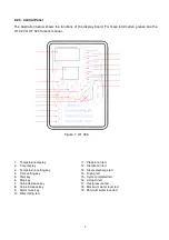
Страница 6: ... Temperature display 11 Preperation led 2 Time display 12 Sterilization led 3 Temperature setting key 13 Steam discharge led 4 Time setting key 14 Drying led 5 6 Start key Stop key 15 16 Cycle completed led Lid open led 7 Value decrease key 17 Overpressure led 8 Value increase key 18 Maximum water level led 9 Alarm mute key 19 Minimum water level led 10 Water filling led ...

Страница 7: ...mperature setting key 13 Steam discharge led 4 Time setting key 14 Drying led 5 6 Drying time Start Stop key 15 16 Cycle completed led Lid open led 7 Value decrease key 17 Overpressure led 8 Value increase key 18 Maximum water level led 9 Alarm mute key 19 Minimum water level led 10 Water filling led ...

Страница 8: ...um pressure switch cuts the power of heaters when the pressure inside the chamber exceeds 3 bar to protect the device and user The minimum pressure switch also prevents door to open if there is a pressure other than zero over zero in the chamber after the sterilization cycle and provides safe operation The second minimum pressure switch equipped in OT 020V is used to start the vacuum pump after th...

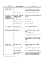
Страница 9: ... according to the following tables Most of the arising problems can be determined by the help of a multimeter The components on the main PCB must not be replaced even the failure is caused by one of the components on the main PCB In this case please send the failed PCB to factory service along with a note on which the failure explanations are written Before replacing the PCB or any control element...

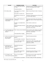
Страница 10: ... connected in reverse 4 The fuse blows frequently Short circuit exists Check the heater with a multimeter If short circuit exists replace the heater Check all solenoid valve bobbins for short circuit with a multimeter If short circuit exits in any bobbin replace it Check the vacuum pump and water pump for short circuit If there is short circuit replace that pump Check all other electrical terminal...

Страница 11: ...fter the operation The air intake selonoid is defective The biological filter is clogged Take the capsule of the solenoid out and clean the core of it if it doesn t solve the problem replace the solenoid valve Replace the fiter 9 The lid is not locked when The locking mechanism is Check the locking mechanism the steam sterilizer defective starts operating The locking bobbin is defective Replace th...

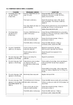
Страница 12: ...id is forced to open Repeat the sterilization operation lightens on the display during the operation after the current operation has finished The lid locking switch is Check the switch and replace it if it is defective defective 4 The error message OFF Power is cut during the Repeat the sterilization appears on the display operation 5 The error message H01 appears on the display Temperature sensor...

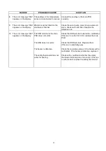
Страница 13: ...he error message H07 appears on the display The SSR terminal of the main PCB does not outlet Check the SSR terminal outlet with a multimeter If there is no outlet 12 VCD replace the main PCB The SSR does not outlet Check the SSR terminals Replace them if there is no electricity pass The heater is defective Check the resistance values of the heater with a multimeter If the heater is defective repla...

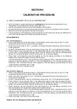
Страница 14: ...nal sensor If the set temperature is 121 C and the external sensor measures 123 C increase the value which appears on the time display by adding 2 if the set temperature is 121 C and the external sensor measures 118 C decrease the value which appears on the time display by subtracting 3 by using value increase or decrease keys 7 8 Press stop to return to stand by mode 4 2 2 OT 020 V Figure 2 Press...

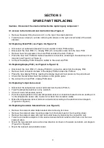
Страница 15: ...e the new display PCB by meeting the display keys and their places on the panel sheet Check that the led lamps meet their places on the plastic panel Re connect the main PCB display PCB cable 5 4 Replacing Temperature sensor Disconnect the temperature sensor terminals from the main PCB 7 Take the temperature sensor out by a wrench Connect a new temperature sensor Put some liquid gasket on the new ...

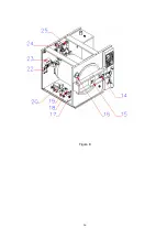
Страница 16: ...er and steam unit diagram Figure 5 or Figure 6 Mount the solenoid valve bobbin socket carefully 5 8 Replacing Vacuum Line Solenoid Valve see Figure 9 Remove the solenoid valve 19 bobbin socket after removing its screw Remove the solenoid valve mounting screw from the bottom of the steam sterilizer Remove the solenoid valve 19 inlet and outlet hoses by loosening its connection nuts Remove the conne...

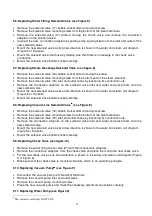
Страница 17: ...Mount the new water level sensor Replace the water tank cover and insulate it by putting liquid gasket Make the electrical connections according to the electrical circuit diagram Figure 3 or Figure 4 5 14 Replacing Heater Disconnect the cables which are connected to the heater terminals Take the shelf carrier 12 and the heater protection sheet 11 out by removing the shelf carrier mounting nut in t...

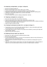
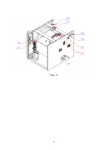
Страница 18: ...Figure 4 Adjust the switching length carefully 5 18 Cleaning The Sterilizatior Chamber Filter see Figure 8 Figure 11 Take the shelf carrier 12 and the heater protection sheet 11 out by removing the shelf carrier mounting screws 34 in the sterilization chamber Take the filter 36 out which is placed on the bottom of the chamber by removing the water inlet record 35 with a wrench Clean the filter por...

Страница 19: ...18 SECTION 6 DIAGRAMS AND DRAWINGS ...

Страница 20: ...19 6 1 ELECTRICAL CIRCUIT DIAGRAM OT 020 Figure 3 ...

Страница 21: ...20 6 2 ELECTRICAL CIRCUIT DIAGRAM OT 020V Figure 4 ...

Страница 22: ...21 6 3 WATER AND STEAM UNIT DIAGRAMS Figure 5 OT 020 flow diagram ...

Страница 23: ...22 Figure 6 OT 020V flow diagram ...

Страница 24: ...23 SECTION 7 SPARE PART LIST ...

Страница 25: ...24 Figure 7 ...

Страница 26: ...25 Figure 8 ...

Страница 27: ...26 Figure 9 ...

Страница 28: ...27 Figure 10 ...

Страница 29: ...28 Figure 11 ...

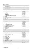
Страница 30: ...6 005 1 15 Lock adjustment screw Z11 V 03 163 1 16 Biological filter Z12 F 06 031 1 17 Water filling solenoid valve Z12 V 01 020 1 18 Steam discharging solenoid valve Z12 V 01 020 1 19 Vacuum line solenoid valve Z12 V 01 020 1 20 Vacuum pump Z12 P 12 006 1 21 Water pump Z12 P 12 007 1 22 SSR Z12 R 07 013 1 23 Filter Z15 F 06 008 1 24 Safety thermostat Z12 T 09 041 1 25 Condense solenoid valve Z12 ...

Страница 31: ...f carrier mounting screw Z11 R 02 237 1 35 Water inlet record Z16 R 02 236 1 36 Filter Z15 F 06 033 1 Temperature sensor sterilization chamber Z19 I 01 036 1 Heater Z15 I 02 111 1 Connector fitting Z12 F 07 019 1 ...

Отзывы: