Page 5 of 15
3. Mounting the wheel hood
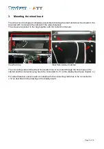
The wheel hood is shipped completely assembled including the shaft and wheel hood switch. It is
mounted with 4 screws to the cabinet of the wheel balancer.
The screws are packed in the bag together with the instruction manual.
View from top
View from inside of cabinet
The connecting cable of the wheel hood switch has to be routed through the bore holes in the
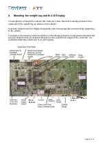
cabinet and the connection plug has to be connected to J 5 on the display board (see chapter. 4.)
For wheel balancer versions with an outside arm the connecting cable has to be connected to
J 12 as described in the drawing on the display board.
Содержание ATT BM 11
Страница 2: ...Page 2 of 15...
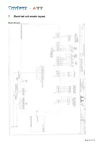
Страница 12: ...Page 12 of 15 7 Electrical schematic layout Basic Board...
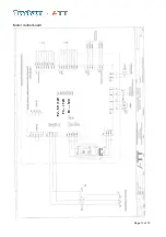
Страница 13: ...Page 13 of 15 Motor control board F2 5V 12V F3 12V F4 12V...
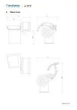
Страница 14: ...Page 14 of 15 8 Dimensions...
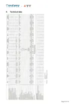
Страница 15: ...Page 15 of 15 9 Technical data...


