4
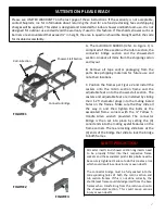
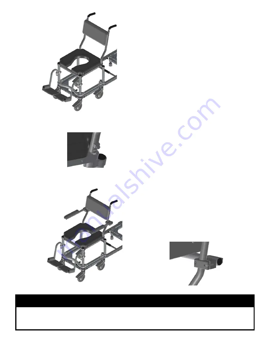
FIGURE 7
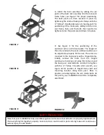
FIGURE 8
FIGURE 9
G. Install the back assembly by sliding the (2)
posts of the back rest assembly into the rear seat
frame holes, see Figure 7 for proper positioning.
The back posts are then secured in place by
tightening the internal back posts clamps with the
¼” Yellow T-Handle Allen wrench. See Figure 8 for
positioning of the back posts sliding into the rear
seat frame holes and the bolts that need to be
tightened once the posts are slid down into place.
H. See Figure 9 for the positioning of the
cantilever arms on the back posts. The height of
the arms relative to the seat and back cushion can
be adjusted to properly fit the user. The arms are
mounted to the back posts with a hinged clamp.
Initially remove the bolts from the hinged
cantilever arm clamps and wrap the clamp around
the back post, reinstall bolts and start to tighten
with the ¼” Yellow T-Handle Allen wrench, see
Figure 10 for position of hinged clamp bolt and
mounting location along back post. Once in
position, securely tighten the arm clamp bolts. At
this point, your mc6000RS should be completely
assembled.
FIGURE 10
SAFETY PRECAUTION!
Now that your mc6000RS is fully assembled, go back and ensure that all bolts are properly tightened and
that everything fits together properly. Failure to do so could result in parts coming loose and could cause
serious injury or even death!


