


DSP LASER AP with MCS
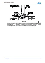
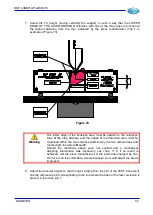
7. Adjust the TX height, moving vertically the support, in such a way that the LOWER
EDGE OF THE LASER EMISSION coincides with one of the three lines in function of
the wished distance from the tool, indicated by the press manufacturer (line 1 in
example of Figure 73).
Figure 73
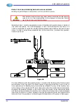
Warning
:
The lower edge of the sensitive area must be parallel to the reference
lines of the stop distance and the edges of the detection area must be
contained within the two surfaces delimited by the two vertical lines and
marked with the letters
R
and
F
.
Should the conditions above were not verified and a mechanical
adjusting intervention was necessary, see chap. 11.4. If no result is
achieved, call the press manufacturer or the personnel charged by him.
Do not act on the collimation screws because you could adjust the beam
improperly.
8. Adjust the receiver height so that the light, exiting from the slot of the TEST instrument,
hits the reference point corresponding to the line where the base of the laser emission is
placed, in this case line 1.
DLAM01EN
93
Содержание DSP LASER AP
Страница 2: ......
Страница 4: ......
Страница 50: ...DSP LASER AP with MCS Figure 34 44 DLAM01EN...
Страница 60: ...DSP LASER AP with MCS Figure 40 54 DLAM01EN...