


DSP LASER AP with MCS
9.1.2. DSP LASER AP
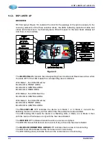
RECEIVER
RX front panel (Figure 19) contains the slots for the passage of the light necessary to the
receiving elements of the three sensitive areas, the LEDs indicating operation modes and
states and references to mechanically place RX with respect to the laser beam already set
and, then, to the machine.
Figure 19
The
BLUE
LEDs
ON indicate the corresponding Front, Central and Rear areas active, while
the state OFF of the LED means the corresponding area is inhibited.
With Mode 1, the LEDs ON will be:
BLUE LED in FRONT AREA
BLUE LED in CENTRAL AREA
BLUE LED in REAR AREA
With Mode 2, the LED ON will be:
BLUE LED in CENTRAL AREA
With Mode 3, the LEDs ON will be:
BLUE LED in FRONT AREA
BLUE LED in CENTRAL AREA
The
YELLOW LED
OFF indicates the device is in Mode 1
or in Mode 2, but with the
Blanking function not active yet, then with all the three detection areas enabled.
The LED blinking ON means the device is in Blanking state, in Mode 2 or in Mode 3, then
with the rear and front areas or only with the rear area disabled.
The
RED LED
OFF indicates that all the active receivers are lighted.
The LED ON means that at least one receiver of any active area has been shaded.
The
BLUE LED HORIZONTAL AREAS
OFF indicates that no area is in Automuting.
The LED fixed ON indicates that the first area is set in Automuting.
The LED blinking slowly indicates that even the central area is in Automuting.
24
DLAM01EN
Содержание DSP LASER AP
Страница 2: ......
Страница 4: ......
Страница 50: ...DSP LASER AP with MCS Figure 34 44 DLAM01EN...
Страница 60: ...DSP LASER AP with MCS Figure 40 54 DLAM01EN...