


07/16/15
Page 6
MANUFACTURER OF DOWN HOLE HAMMERS AND BITS
Champion
®
®
®
®
®
RC160
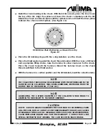
CAUTION
THE ACCEPTABLE CLAMPING AREAS START 8" (203 MM) FROM EITHER CASE END, TO
AN ADDITIONAL 10" (254 MM) BEYOND THIS POINT. PLACING THE VISETONG ON THE
AREA OF THE CASE WHERE THE PISTON CYCLES CAN DISTORT THE CASE, RESTRICT
PISTON MOVEMENT AND VOID THE WARRANTY.
•••••
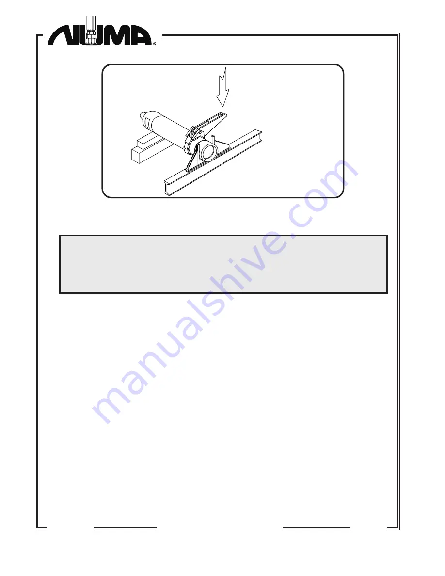
With the chuck secured in the fork wrench, (see figure 2-1) loosen the joint by turning
the case with the visetongs. Remove the hammer from the wrench and reverse the
hammer end to end in the hammer stand / wrench. With the backhead flats secured
in the fork wrench (see figure 2-1), loosen the joint by turning the case with the
visetongs.
•••••
With the crane or lift truck, move the hammer into an upright position with the chuck
end down. With an adequate lifting device, lift and support the hammer while
unscrewing the chuck. After setting the hammer down, and while lifting and
supporting the backhead, unscrew and remove the backhead from the case.
•••••
Remove the backhead o-ring and thrust washer from the backhead.
•••••
Remove the collection tube o-ring from the backhead I.D. on the drill rod mating
end.
•••••
Remove the check valve seat, the check valve and the check valve spring from the
backhead end of the case. The check valve seat is equipped with two 1/2" (13 mm)
UNC tapped holes for lifting eyes to facilitate removal.
•••••
Using a small screwdriver, pick the check valve seat o-ring from the outside diameter
of the check valve seat.
Hammer Stand/Wrench Diagram
Figure 2-1
Pulldown Visetongs
Petol No. VTDA120
Force Direction Required:
15,000 - 25,000 lbs.
(6,800 - 11,400 Kg.)
Blocking to
height of stand
Hammer stand and wrench
combination, structural steel,
I-Beam, weld construction
bracing to suit.
Champion
RC160