NuAire BPS T-ES Скачать руководство пользователя страница 2

2

31. 08. 21. Document Number  671746

Nuaire | Western Industrial Estate | Caerphilly | CF83 1NA | nuaire.co.uk

BPS (V/T)-ES

Installation Manual

1.2 Important Information

This manual contains important information on the safe and 
appropriate assembly, transport, commissioning, operation, 
maintenance, disassembly and simple troubleshooting of the product.

While the product has been manufactured according to the accepted 
rules of current technology, there is still a danger of personal injury or 
damage to equipment if the following general safety instructions and 
the warnings contained in these instructions are not complied with.

Read these instructions completely and thoroughly before 
working with the product.

Keep these instructions in a location where they are accessible 
to all users at all times.

Always include the operating instructions when you pass the 
product on to third parties.

1.3 Personal Protective Equipment

The following minimum Personal Protective Equipment (PPE) is 
recommended when interacting with Nuaire products:

Protective Steel Toed Shoes - 

when handling heavy objects.


Full Finger Gloves (Marigold PU800 or equivalent) - 

when 

handling sheet metal components. 

Semi Fingerless Gloves (Marigold PU3000 3DO or equivalent) 

- when conducting light work on the unit requiring tactile 
dexterity. 

Safety Glasses

 - when conducting any cleaning/cutting operation 

or exchanging filters. 

Reusable Half Mask Respirators 

- when replacing filters which 

have been in contact with normal room or environmental air.

Nuaire would always recommend a site specific risk assessment by a 
competent person to determine if any additional PPE is required. 
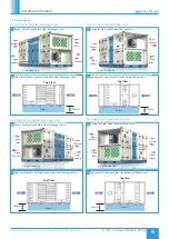
2.0 INTRODUCTION

The information contained in this document provides details of 
installation, operation and maintenance for installers and users of the 
BOXER PACKAGED SOLUTION (BPS) AHU units with heat recovery.

The BPS AHU range, is manufactured from Aluzinc corrosion resistant 
steel, with 50mm double skinned panels and anodized aluminium 
frame of a totally thermally-broken design, complying with the 
following specification in accordance with BS EN 1886: Mechanical 
strength, D1; Leakage class, L1; Thermal transmittance, T2; Thermal 
bridging, TB1.

This range includes high efficiency centrifugal fans with EC motors, a 
high efficiency thermal wheel or plate heat exchanger, G4 pre-filtration 
and F7 main filtration of the supply air and M5 filtration of the extract 
air. 

Optional heating (LPHW or Electric) model variants are available. 
Ancillaries including but not limited to attenuators, dampers, weather 
terminals and frost modules are available from Nuaire.

These units are supplemented with the EcoSmart Classic (ES) control 
platform. General information regarding performance and specification 
for the equipment is available via our technical literature, and/or 
project specific documentation.

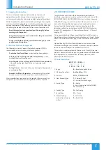
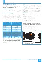
2.1 Code Description: 

B 8 17 V / L R / ES - L

|   |   |   |     |  |      |      |

1  2  3 4    5 6     7    8

1. Range:  


= Boxer Packaged Solution

2. ErP Compliance Year: 

8 or No Affix 

= 2018

3. Unit Size:


07, 12, 17, 22, 32 

or

 42

4. Heat Recovery Type: 

T

 = Thermal Wheel 


= Vertical Plate Exchanger

5. Heating Type:   

E

 = Electric 


= Low Pressure Hot Water (LPHW) 


= No Heating

6. Cooling Type: 


= No Cooling

7. Control Type: 


ES

 = Classic

8. Access Handing   

= Left Hand 

(in direction of supply  

= Right Hand 

airflow)

Содержание BPS T-ES

Страница 1: ... manufacturer its service agent or similarly qualified persons in order to avoid a hazard Precautions must be taken to avoid the back flow of gases into the room from the open flue of gas or other fuel burning appliances This appliance should not be used by children or persons with reduced physical sensory or mental capabilities or lack of experience and knowledge unless they have been given super...

Страница 2: ...commend a site specific risk assessment by a competent person to determine if any additional PPE is required 2 0 INTRODUCTION The information contained in this document provides details of installation operation and maintenance for installers and users of the BOXER PACKAGED SOLUTION BPS AHU units with heat recovery The BPS AHU range is manufactured from Aluzinc corrosion resistant steel with 50mm ...

Страница 3: ... Handed for Vertical PHX Units B AT FE R BPS size Frost Coil Electric 36kW Right Handed for Thermal Wheel Units B AT FE L BPS size Frost Coil Electric 36kW Left Handed for Thermal Wheel Units Frost Coil LPHW 3 B AV FL R BPS size Frost Coil LPHW Right Handed for Vertical PHX Units B AV FL L BPS size Frost Coil LPHW Left Handed for Vertical PHX Units B AT FL R BPS size Frost Coil LPHW Right Handed f...

Страница 4: ...uare lifting holes at the end of each side to enable lifting In addition to this covered fork lifting channels are located across the width of the base frame if the module length is sufficient to allow this For shorter modules the fork lifting points will be along the length of the section without a covered channel Figure 3 Only individual modules should be lifted or manoeuvred The units must not ...

Страница 5: ...nal time should be allocated For convenience it is preferred that wherever possible this minimum access provision is not adopted and it is recommended that a minimum of around 600mm clearance as stated in ADF 2010 is allowed Where these arrangements are not suitable the Consultant s and Contractor s project specific requirements will always be accommodated where possible 5 1 Hinged Removable Panel...

Страница 6: ...ight Hand Thermal Wheel Units SUPPLY SUPPLY CONTROLS Access 600mm Top View 14 Top View of Access For Right Hand Thermal Wheel Units 5 2 Access Areas 5 2 1 Left Hand Plate Heat Exchanger Units Open Extract Open Inlet Open Supply Left Hand Unit Open Exhaust 7 Access For Left Hand Plate Heat Exchanger Units SUPPLY SUPPLY BYPASS CONTROLS Access Top View 600mm 8 Top View of Access For Left Hand Plate H...

Страница 7: ...ible for the units failing a site leakage test if the above have not been carried out correctly 6 3 Module Joints After unwrapping temporarily remove the rubber weatherproof cover strip and M10 base frame bolts from any modules and store in a safe location for later use Apply the sealing gasket as necessary to the mating faces of the unit frames Typically the sealing gaskets are pre fitted to the ...

Страница 8: ...pment must not be exposed to the weather in an unassembled or partially assembled state All roof terminal ductwork sealing and assembly work must be completed before the unit can be considered weather resistant 6 8 Unit Connections 6 8 1 Ducting Nuaire do not provide ductwork connections with units instead the open ended framework should be utilised Flanged connections are available as an option r...

Страница 9: ...out the requirement of removing the roof terminal Figure 22 21 Removing Roof Terminal 22 Actuator Access 6 11 Damper Roof Terminal Assembly The inlet outlet dampers and roof terminals are pre assembled for BPS sizes 07 12 and 17 on a double skinned and insulated panel The panel is easily fitted to the unit with a series of quarter turns provided with a locking key Figure 23 For the larger size BPS...

Страница 10: ... B 42T ES 22 5 A 22 5 A 52 5 A 52 5 A Denotes any Character These heater models require a separate power supply for the electric heater section with an appropriate over current protection device These heater models require two separate power supplies for the two 2 electric heater sections each with an appropriate over current protection device 7 4 Wiring All inter connections between circuit board...

Страница 11: ...y R Right Hand airflow 7 7 Wiring Diagram Reference Table Unit Size Unit Contains NO Heater Unit Contains LPHW Heater Unit Contains Electric Heater 07 Section 7 8 1 Section 7 8 3 Section 7 8 5 12 Section 7 8 1 Section 7 8 3 Section 7 8 5 17 Section 7 8 2 Section 7 8 4 Section 7 8 6 22 Section 7 8 2 Section 7 8 4 Section 7 8 6 32 Section 7 8 2 Section 7 8 4 Section 7 8 7 42 Section 7 8 2 Section 7 ...

Страница 12: ...ard ecosmart Min Trickle 0 1 Test Max SL Runon P w r S ta n d b y F a n 1 F a n 2 H e a ti n g C o o li n g F a u lt F ro s t T x R x 0 24V 15V 0 15V 230V 400V Condensate Pump HX Bypass Relay Heat Exchanger Bypass Board ABB 0 0FF ABB 0 0FF ABB 0 0FF ABB 0 0FF ABB 0 0FF ABB 0 0FF ABB 0 0FF ABB 0 0FF N L1 L2 L3 E Lighting Thermal Wheel 24Vac TR Controls Extract Fan Supply Fan Fan Run Relay HX Bypass...

Страница 13: ...ing Fault Frost Tx Rx Extract Fan Board Condensate Pump HX Bypass Relay Lighting Thermal Wheel Transformer 230Vac Supply Fan Contactor Extract Fan Contactor 0 24V 15V 0 15V 230V 400V ecosmart Min Trickle 0 1 Test Max SL Runon Pwr Standby Fan 1 Fan 2 Heating Cooling Fault Frost Tx Rx Fan Run Relay HX Bypass Relay 24Vac Fuse 1 6A Thermal Wheel Fault Contacts NC T14 15 Supply Filter dP Contacts NC T1...

Страница 14: ...a n 2 H e a ti n g C o o li n g F a u lt F ro s t T x R x 0 24V 15V 0 15V 230V 400V Condensate Pump HX Bypass Relay Heat Exchanger Bypass Board ABB 0 0FF ABB 0 0FF ABB 0 0FF ABB 0 0FF ABB 0 0FF ABB 0 0FF ABB 0 0FF ABB 0 0FF N L1 L2 L3 E Lighting Thermal Wheel 24Vac TR Controls Extract Fan Supply Fan Fan Run Relay HX Bypass Relay 24Vac Fuse 1 6A Thermal Wheel Fault Contacts NC T14 15 Supply Filter ...

Страница 15: ...ate Pump HX Bypass Relay Lighting Thermal Wheel Transformer 230Vac Supply Fan Contactor Extract Fan Contactor 0 24V 15V 0 15V 230V 400V ecosmart Min Trickle 0 1 Test Max SL Runon Pwr Standby Fan 1 Fan 2 Heating Cooling Fault Frost Tx Rx Fan Run Relay HX Bypass Relay 24Vac Fuse 1 6A Thermal Wheel Fault Contacts NC T14 15 Supply Filter dP Contacts NC T12 13 Extract Filter dP Contacts NC T10 11 24Vac...

Страница 16: ...ABB 0 0FF ABB 0 0FF ABB 0 0FF ABB 0 0FF ABB 0 0FF N L1 L2 L3 E Lighting Thermal Wheel 24Vac TR Controls Extract Fan Supply Fan Fan Run Relay HX Bypass Relay 24Vac Fuse 1 6A Thermal Wheel Fault Contacts NC T14 15 Supply Filter dP Contacts NC T12 13 Extract Filter dP Contacts NC T10 11 24Vac 0V IO Damper Relay 400V 3ph 50Hz Main Power Supply Overcurrent Protection By Others Local Rotary Lockable IP6...

Страница 17: ...n 1 Fan 2 Heating Cooling Fault Frost Tx Rx Fan Run Relay HX Bypass Relay 24Vac Fuse 1 6A Thermal Wheel Fault Contacts NC T14 15 Supply Filter dP Contacts NC T12 13 Extract Filter dP Contacts NC T10 11 24Vac 0V IO Damper Relay 400V 3ph 50Hz Main Power Supply Overcurrent Protection By Others Local Rotary Lockable IP66 67 Isolator L1 E L2 L3 N L1 L2 L3 N T1 T2 T3 N 1 2 3 4 All internal connetions be...

Страница 18: ...4Vac Fuse 1 6A Thermal Wheel Fault Contacts NC T14 15 Supply Filter dP Contacts NC T12 13 Extract Filter dP Contacts NC T10 11 24Vac 0V IO Damper Relay 400V 3ph 50Hz Main Power Supply Overcurrent Protection By Others Local Rotary Lockable IP66 67 Isolator L1 E L2 L3 N L1 L2 L3 N T1 T2 T3 N 1 2 3 4 400V 3ph 50Hz Main Power Supply Overcurrent Protection By Others Local Rotary Lockable IP66 67 Isolat...

Страница 19: ...ill reset but a power cycle is required to reset the heater supply contactor The frost coil is fitted with a burst fired controller with integral set point air off thermistor air in frost stat thermal cut out and contactor The burst fired controller is only enabled if the frost stat reads a frost condition the over temperature cut out is healthy AND a 24vac fan run signal is received from the main...

Страница 20: ...ating Cooling Fault Frost TX RX Connector Ecosmart 39 Ecosmart Commissioning Board 9 4 Settings 9 4 1 Maximum Airflow Ensure the power supply is switched off and that a link wire is connected from the supply L to the SL terminal Unplug all items connected to the Net connectors Switch on the power supply Wait for the fan to complete its self test operation Measure the airflow using standard commiss...

Страница 21: ...vy duty operation maintenance intervals are to be established by the operator 11 4 Filters When removing the filter access panels pay attention to the airflow direction marked on the panel this must be replaced to the exact position prior to being removed Disposable filters should be checked and changed when they become fully laden with dust Washable filters should be removed and washed in a mild ...

Страница 22: ...its or by spraying with a mild detergent solution for grease deposits Solvents strong alkaline acidic or any products that may be aggressive to aluminium or plastics should not be used Do not use cleaning water over 50 C Drain lines should be checked to ensure that they are unobstructed and free draining Traps should be checked that they are fully primed and functioning Drain pans should be flushe...

Страница 23: ...and any dust removed Check any thermal wheel belt motor bearings seals and if necessary clean with a soft brush or vacuum cleaner 12 0 WARRANTY The 5 year warranty starts from the day of delivery and includes parts and labour for the first year The remaining period covers replacement parts only This warranty is void if the equipment is modified without authorisation is incorrectly applied misused ...

Страница 24: ...rate provision for support 4 3 Flanges and connection spigots are provided for the purpose of joining to duct work systems They must not be used to support the ductwork 4 4 Local Environment Humidity Ambient humidity the humidity at the unit s installed location shall be within the range 10 to 95 for controls non condensing Air humidity the humidity of the air passing through the unit shall be wit...

Отзывы: