Matrix
Installation and Operation Instructions
Mandatory Pre-commissioning Procedure for Plastic Venting (PVC or CPVC)
Do not apply power to the boiler prior to Step 4 in the Mandatory Pre-commissioning
Procedure for Plastic Venting.
1)
Working with the power turned off to the boiler, completely install the vent and air-inlet system, securely
cementing joints together. If possible, allow primers/cements to cure for 8 hours before firing the burner. If
curing time is less than 8 hours, proceed with Steps 2 through 6.
2)
Maintain the boiler gas supply shut-off valve in the off position.
3)
Disconnect electrical leads to the Hot Surface or Spark Igniter. Ensure the cables are placed in a fashion
where they will not arc to ground or other conductor. Refer to warning regarding Spark Igniter Cable.
4)
Turn power on to the boiler and apply a heat demand.
5)
Allow for 3 complete trials for ignition, consisting of pre and post purge of the combustion blower, until an
ignition lockout occurs. Repeat the process two more times (i.e. 9 complete ignition sequences in total).
6)
Turn power off and reconnect the electrical leads to the Igniter.
Near Boiler Vent/Air-inlet Piping
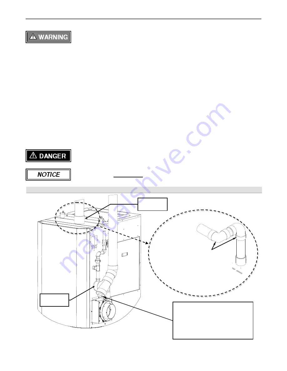
The Matrix air-inlet and exhaust fittings are 3” male PVC; use approved cement to secure to the venting system
(see Table 4-2). Check the flue outlet gasket (inside the boiler cabinet) for proper insertion and sealing prior to
and after attaching the venting. Ensure the venting system does not apply a load or stain on the flue outlet of the
boiler; this manufacturer recommends using two elbows to create a “swing joint”; see Figure 4-1.
Exhaust venting must be supported to reduce strain on piping joints. Failure to
follow these instructions may result in result in damage, serious injury or death.
In Canada, the first
3 ft (915 mm)
of vent piping must be readily accessible for inspection.
Figure 4-1 Near Boiler Venting
Air-Inlet
- check with applicable local codes for acceptable pipe material.
It is recommended to have a collection point
for condensation in the intake venting.
Condensation can then be drained to an open
house drain or condensate pump.
Drain line from intake must have an
appropriate trap or shut off valve to avoid
siphoning.
It is recommended that two elbows be used,
so that the slope of the horizontal exhaust
vent does not affect the vertical plumb of the
pipe connected to the boiler. Slope all
horizontal indoor exhaust venting ¼” to ½”
per linear foot.
Exhaust
Connection
Air-inlet
Connection
Содержание Matrix
Страница 18: ...Matrix Installation and Operation Instructions Figure 5 1 Termination Clearances Quick Reference Diagram ...
Страница 41: ...Matrix Installation and Operation Instructions 41 Figure 12 2 Low Voltage Field Wiring ...
Страница 55: ...Matrix Installation and Operation Instructions 55 16 0 WIRING SCHEMATICS Figure 14 1 a Connection Diagram ...
Страница 56: ...Installation and Operation Instructions Matrix 56 Figure 14 1 b Ladder Logic Diagram ...
Страница 71: ...Matrix Installation and Operation Instructions 71 NOTES ...


