background image


Page 18 of 22


© Brüel & Kjær Vibro 

● C107759.002 / V03 


Technical alterations reserved! 

EN 


UNRESTRICTED DOCUMENT 

4.7 

Document the completed commissioning process 

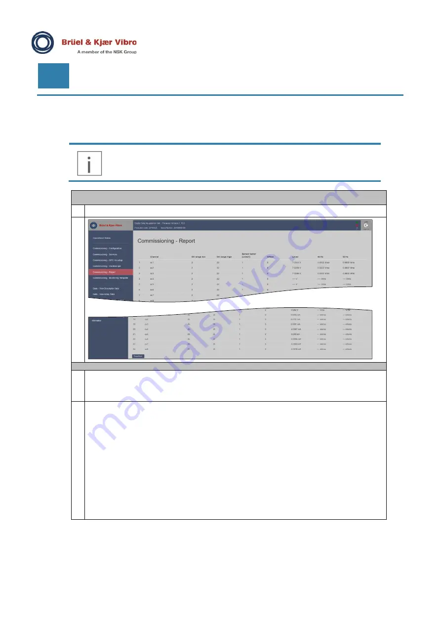
Use the Commissioning Report feature to document the final commissioning result. 


IMPORTANT NOTE! 

Send the commissioning reports to the back office (B&K Vibro Hotline) staff.  
It is valuable information in case of problems with connections to the VCM-3. 


View Commissioning Report 

Select Commissioning Report from the VCM-3 Homepage menu 


Download the Commissioning Report to the service PC 

Save the report by clicking 

Save/Print

 at the bottom of the Commissioning Report page. 

A print window is automatically opened. Select the save to PDF feature in the print window. 
Save the report with a turbine name or number and the IP address. Then it is so it easy to recognize 
again. 

The saved Commissioning report contains: 


Machine Name 


Machine Number 


Firmware Version 


Serial Number of VCM-3 


IP Address 


MAC Address 


Default Gateway 


Netmask 


DNS Server 


Enabled services 


Active monitoring template 


Identification of the user 


Bias voltages and 50/60Hz noise. 


Содержание Bruel & Kjaer Vibro VCM-3

Страница 1: ...Keep it accessible for future reference UNRESTRICTED DOCUMENT Instruction VIBRO Condition Monitoring 3 VCM 3 On site Commissioning ...

Страница 2: ...428 0 Fax 49 6151 428 1000 Brüel Kjær Vibro A S Lyngby Hovedgade 94 5 sal 2800 Lyngby Denmark Phone 45 69 89 03 00 Fax 45 69 89 03 01 BK Vibro America Inc 1100 Mark Circle Gardnerville NV 89410 USA Phone 1 775 552 3110 Hotline Phone 49 6151 428 1400 E Mail support bkvibro com Homepage www bkvibro com Corporate E Mail info bkvibro com Trademarks and Copyrights All trademarks service marks and or re...

Страница 3: ... up 9 3 1 1 Sensor problems on connected sensors signal inputs 9 3 1 2 CCS constant current supply sensors 9 3 1 3 Non CCS sensors 10 3 1 4 VCM 3 hardware device problems 10 4 VCM 3 Homepage Commissioning Procedure 12 4 1 Log into the VCM 3 Homepage 12 4 2 Check the VCM 3 firmware version and update firmware 13 4 3 Check the Operational Status 14 4 4 Check bias voltages of sensors 15 4 5 Make tap ...

Страница 4: ... is running by default in the VCM 3 when it is started up for the on site commissioning procedure When the on site commissioning procedure has been completed the monitoring template which will provide the VCM 3 with the correct personality for the particular machine type can be uploaded to the VCM 3 Homepage and activated on the device NOTE The procedures described in this instruction assume that ...

Страница 5: ...al differences in what a LED color means Always use a manual that match the Firmware version you have 1 3 Document Conventions Feature Comments Menu items buttons tabs UI features keyboard instruction Indicated by bold type face Examples Click Remove Press Ctrl Shift or Press F12 Path denotations Example File Template Load template Important Note Important Note indicates information which is poten...

Страница 6: ...vice laptop with 1 A Microsoft Edge browser or Mozilla Firefox browser Due to the installed security certificates on the VCM 3 the Google Chrome browser has difficulties in showing the VCM 3 Homepage When you address the VCM 3 Homepage in either Microsoft Edge or Firefox some security alerts are shown These shall be ignored 2 The latest VCM 3 firmware version This is optional Only to be used if yo...

Страница 7: ...g the factory monitoring template Power Up 1 Apply power to the VCM 3 2 Wait until the boot procedure is complete When the Boot Status LED turns into green the boot procedure is complete All channels in the VCM 3 have been configured in the factory monitoring template Therefore you will see a blue color LED on the AC DC channels with no sensor connection After power up the VCM 3 front panel shall ...

Страница 8: ...d in the factory template DO Off as the digital output is not in use DI Off as the digital input is not in use AC DC On Green input channels which are wired to an accelerometer In this example channel 1 to 9 AC DC On Blue input channels which are configured as constant current source CCS accelerometers but not wired to an accelerometer AC DC 11 and 12 On Blue input channels which are configured fo...

Страница 9: ...lue Channel voltage out of defined range Tacho out of range for tacho channels Yellow blinking Level 3 indication is controlled by the template the blinking is combined with red green or blue If there is an error indication on the channel LED it is important to know what type of sensor you are working with There are two types of sensors 3 1 2 CCS constant current supply sensors Color Explanation B...

Страница 10: ...you should check the sensor 3 1 4 VCM 3 hardware device problems System LED Color Explanation Green Connected to backend Yellow Disconnected from backend was previously connected Blue Disconnected from backend Red Watchdog error reboot imminent White Firmware is upgrading Purple System is sampling real time Cyan System has stopped real time sampling Template LED Color Explanation Green Template lo...

Страница 11: ...oot activates some repair facilities 2 If 1 does not help then make an upgrade of the firmware Refer to the procedure in Appendix 2 3 If 2 does not help the VCM 3 has a fault You cannot complete the commissioning procedure Exchange the VCM 3 with a spare unit Status Online On Red Either default gateway cannot be reached but before or network has a configuration error Maybe the specified IP address...

Страница 12: ...onfigure the VCM 3 with the correct IP addresses and enable services 7 Save the commissioning report 8 Reboot the VCM 3 after completion 9 Inspect the VCM 3 front plate after reboot 4 1 Log into the VCM 3 Homepage How to connect a laptop and perform the login 1 Change the laptop network settings to match the ip range of the VCM 3 Factory default network settings of VCM 3 are as follows Netmask sub...

Страница 13: ...wing credentials Username vcm_service Password VCM3 Service 4 2 Check the VCM 3 firmware version and update firmware Check firmware version 1 After the login procedure is completed chack the firmware version number is located in the page header 2 If the firmware is version 1 14 or lower the VCM 3 must be updated to a later version Refer to the procedure in Appendix 2 Initial first release firmware...

Страница 14: ...ust have the status as shown on the screen shot Otherwise there is a problem with the VCM 3 The other status indicators are dependent upon the state of the commissioning procedure 2 If the status indicators in the red boxes shows a different result try to reboot the VCM 3 and inspect the Operational Status page again 1 Reboot the VCM 3 and check if the problem disappears The reboot activates some ...

Страница 15: ...onitoring Template which is not to be exchanged with the Standard Master Monitoring Template and or the customized Monitoring Template created with the VCM 3 Editor software View Commissioning Report 1 Select Commissioning Report from the VCM 3 Homepage menu 2 Inspect the report The bias voltages Level of CCS sensor shall be between 11 and 14 Volts The bias voltages Level of the AS 247 MEMS sensor...

Страница 16: ...ry monitoring template the Oscilloscope plot can freeze or the VCM 3 Homepage becomes unresponsive When this condition occurs the user usually has to call up another function on the VCM 3 homepage and then return to the Oscilloscope view IMPORTANT NOTE The measurement functionality of the VCM 3 is not affected by this behavior All measurement functions of the VCM 3 hardware firmware continue to ru...

Страница 17: ...ides a valid signal 4 6 Configuration IMPORTANT NOTE It is essential that this manual process is done correct otherwise you may require an extra visit to rectify the information Configure network and machine specification Select the Commissioning Configuration Page on the VCM 3 Homepage On the Commissioning Configuration page key in the network configuration Name Enter a machine name Number Enter ...

Страница 18: ...g Report from the VCM 3 Homepage menu 2 Download the Commissioning Report to the service PC 1 Save the report by clicking Save Print at the bottom of the Commissioning Report page A print window is automatically opened Select the save to PDF feature in the print window Save the report with a turbine name or number and the IP address Then it is so it easy to recognize again 2 The saved Commissionin...

Страница 19: ...late The factory template is loaded and running Status Online A green color shows that the VCM 3 can ping the specified gateway This tells that the VCM 3 is integrated into the network setup Boot Status On Green This indicates the the VCM 3 has completed it s boot procedure DI O On Green as Modbus is enabled in the factory template DO Off as the digital output is not in use DI Off as the digital i...

Страница 20: ... 002 V03 Technical alterations reserved EN UNRESTRICTED DOCUMENT 5 Appendix 1 Update VCM 3 firmware Contact Brüel Kjær Vibro Technical support support bkvibro com to get information and support in case a device upgraded updated is necessary ...

Страница 21: ...tarts running Power Down procedure Action Boot Status LED Explanation Power Down Normal Press the power switch for 3 seconds Soft Power down will close down the VCM 3 in an orderly manner where it is ensured that all data is stored in non volatile memory before power is taken off Push the button for approximately 3 sec until the Boot Status LED starts flashing orange green Release the button The p...

Страница 22: ...ro A S Lyngby Hovedgade 94 5 sal 2800 Lyngby Denmark Phone 45 69 89 03 00 Fax 45 69 89 03 01 BK Vibro America Inc 1100 Mark Circle Gardnerville NV 89410 USA Phone 1 775 552 3110 Corporate E Mail info bkvibro com Homepage www bkvibro com VCM 3 On Site Commissioning Brüel Kjær Vibro 03 2022 C107759 002 V03 Technical alterations reserved ...

Отзывы: