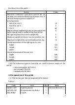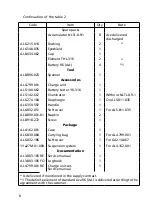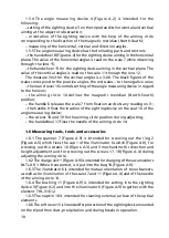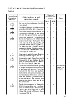
3
2.7 During breaks in work and in bad weather, it is necessary to put the soft
cover 5 on the sighting device.
2.8 If some bright glowing objects come into the field of view, it is necessary
to switch the sighting device off by turning the handle 2 (Figure A.3) to the
position marked by the red point.
2.9 Switch the sighting device off after finishing work.
2.0 Be sure if the sighting device 4 (Figure A.0), the angle measuring device 2,
the tripod 3 and the STA kit are put and fastened in the case correctly.
2. Do not connect the sighting device to other power supplies except the
accumulators 4 (Figure A.9), elements 2 or 3.
2.2 Do not place the sighting device near the sources of magnetic fields.
2.3 It is recommended to remove the accumulators from the sighting device
and from the illuminator and keep them in the pocket of the uniform before
and after working with the device. It is done in order to prevent accidental
switching on the power supply. When the temperatures are below zero, it also
allows to extend the time of the accumulators operation.
3 PREOPERATION INSTRuCTIONS
3.1 General instructions
3.. While working with the sighting device under the conditions which
require the high degree of camouflage, fix the Eye shield 2 (Figure A.9) on it,
for that do the following:
– take the clamp 6 (Figure A.3) off the eye shield 7;
– dismount the eye shield 7;
– take the eye shield 2 (Figure A.9) from the single STA kit;
– put the eye shield 2 on the ocular ring, for that slightly spread the Eye
shield;
– put the clamp 6 on the Eye shield 2 (Figure A.3).
3..2 If there are no charged accumulators 4 (Figure A.9) available, use the
element 3 or the element 2 with the bushing as a power supply. Replace
them in the following way:
– switch the sighting device off;
– screw out the cap (Figure A.3) with the accumulators NLTs-0.9-;
– take the accumulators NLTs-0.9- out of the cup of the cap ;
– put the elements 3 (Figure A.9) or the element 2 with the bushing
inside the sighting device; mind the polarity indicated on the elements and on
the cup of the cap (Figure A.3);
– screw the cap up;
– switch on the sighting device, check the brightness of the IIT screen and
switch the sighting device off.
Replace the power supply of the illuminator shown in the figure A.5 in the
same way.
Содержание 1PN91-2
Страница 1: ...ARTICLE 1PN91 2 Service manual AL3 803 105 RE...
Страница 2: ......
Страница 37: ...37 2 1 3 1 cap 2 ring 3 cap Figure A 5 The illuminator...
Страница 38: ...38 Figure A 6 The field of view of the sighting device...
Страница 39: ...39 Figure A 7 The Landolt ring for checking illumination...
Страница 40: ...40 Figure A 8 The chart for illumination defining Illumination lux distance m...
Страница 43: ...43 1 91 2...


