

TEMPERATURE AND HUMIDITY CONTROLLER
N322RHT
OPERATING MANUAL V1.7X H
Man 5001234
The N322RHT is a digital controller for relative humidity and temperature. Its 2 relay outputs can be
configured independently as control or alarm, either for temperature or relative humidity.
The humidity and temperature sensor, sold separately, is protected by a polyamide capsule and have 3 or
6 meters long cables.
The features of a particular model (mains supply, digital communication, etc) are identified by the label
placed on the controller body.
SPECIFICATIONS
Sensor Input: Humidity measurement
Range:
0 and 100 % RH;
Accuracy:
Refer to
Fig. 1
;
Repeatability
: ± 1 % RH;
Hysteresis:
± 1 % RH;
Linearity error:
<< 1 % RH;
Stability:
< 1 % RH / year;
Response time:
Around 8 s to reach 63 % of a fast input change. Valid at 25 °C and 1 m/s airflow.
Sensor Input: Temperature measurement
Accuracy:
Refer to
Fig. 1
;
Repeatability:
±0,1 °C;
Range:
-20 and 100 °C;
Response time:
up to 30 seconds in slow moving air.
Warm-up:
....................................................................................................................................... 15 minutes
Measurement resolution:
RH:
..................................................................................... 1 %
T
: ...................................................... 0.1º from –19,9 to 119.9º
Note
: The equipment keeps its precision all over the range, despite the lack of display resolution in a part
of the range does not allow its visualization.
OUTPUT1:
................................................... Relay SPDT; 1 HP 250 Vac / 1/3 HP 125 Vac (16 A Resistive)
............................................................................................... Optional: Pulse, 5 Vdc, 25 mA max.
OUTPUT2:
............................................................................................................. Relay: 3A / 250 Vac, SPST
POWER SUPPLY:
Tension: ........................................... 100~240 Vac/dc (± 10 %)
Optional: .......................................... 24 Vdc/ac (12~30 Vdc/ac)
Frequency:................................................................. 50~60 Hz
Consumption: .................................................................... 5 VA
Dimensions
:
Width x Height x Depth: ............................................................. 75 x 33 x75 mm
Weight: ........................................................................................................ 100 g
Panel cut-out: .................................................................................... 70 x 29 mm
Electronic module operating environment
....................................................... 0 to 40 °C / 20 to 85 % UR
Sensor module operating environment
: ...................................................... -20 to 100 °C / 0 to 100 % UR
Case: Polycarbonate UL94 V-2
Protection: box IP42, front panel IP65, sensors capsule IP40 (sold separately)
Suitable wiring: Up to 4.0 mm²
RS-485 digital communication; RTU MODBUS protocol (optional)
Serial interface not isolated from input circuitry.
Input circuitry isolated from power supply, except in the 24 V powered model.
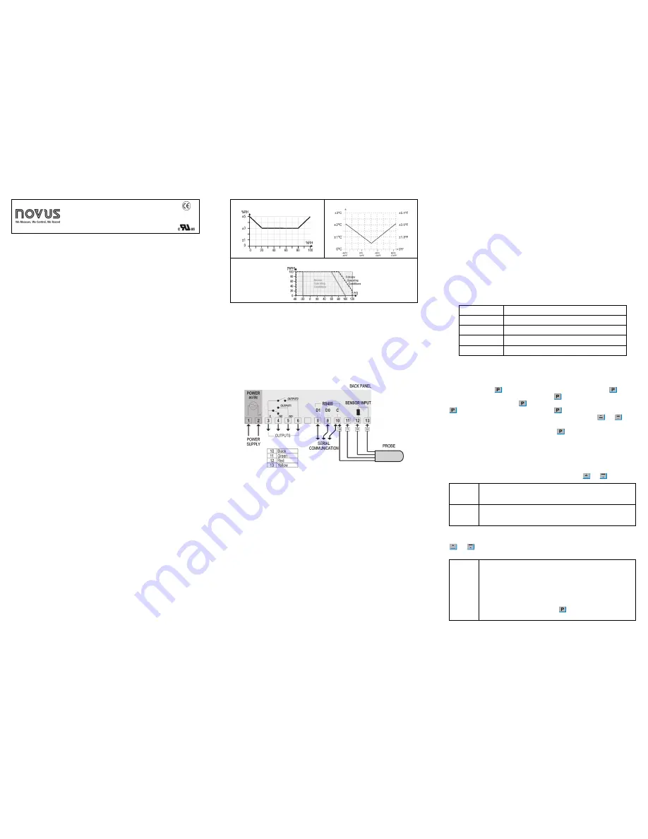
Relative Humidity Accuracy at 25 °C
Temperature Accuracy
Sensor Operating Conditions
Fig. 1
- RH and Temperature accuracies
IMPORTANT
The sensor used in this controller may be damaged or lose calibration if exposed to aggressive
atmospheres with high concentrations as Chloride Acid, Nitride Acid, Sulphuric Acid or Ammonia.
Acetone, Ethanol and Propylene Glycol may cause reversible measurement drifts.
Fine trimming in the indication of RH and Temperature are available at the parameters
0fk
and
0ft
, in
the configuration level of parameters.
ELECTRICAL WIRING
The figure below indicates the connection to the sensor, power supply and controller output, as well as a
connection example.
Fig. 2
– N322RHT terminals
Recommendations for installation
The humidity sensor Conductors shall go through the system plant separately from the control and feeding
output conductors, if possible in grounded electrical ducts.
The controller feeding shall be preferably provided from a proper instrumentation network with a phase
different from the one used for the control output.
It is recommendable to use RC FILTERS (47 R and 100 nF, series) in contactor coils, solenoids, etc.
WORKING WITH THE CONTROLLER
Multiple output controllers are suited for controlling multiple stage systems.
Other applications require OUTPUT 1 to be the control output and OUTPUT 2 to be the alarm.
There are eight distinct alarm functions implemented in OUTPUT 2, selected by the parameter
Ac2
,
described below:
2
- Low alarm – OUTPUT 2 is turned on when the selected variable, as assigned for OUTPUT 2 in
the
(nt
parameter, falls
below
the
SP2
value.
3
- High alarm – OUTPUT 2 is turned on when the selected variable exceeds the value
programmed in
SP2
.
4
- Inside range alarm – OUTPUT 2 is turned on when the selected variable is within the range
defined by:
(
SP1
–
SP2
)
and
(
SP1
+
SP2
)
5
- Outside range alarm: OUTPUT 2 is turned on when the selected variable falls outside the
range defined by:
(
SP1
–
SP2
)
and
(
SP1
+
SP2
)
Functions
6
,
7
,
8
and
9
are identical to the above ones except that they incorporate the Initial Blocking
feature, which inhibits the output if an alarm condition is present at start-up. The alarm will be unblocked
after the process reaches a non-alarm condition for the first time.
Note
: The action modes 6, 7, 8 and 9 are available to OUTPUT2 only when
(NT
is set to 0 or 3.
In a multiple stage application,
SP1
and
SP2
are configured to operate at different settings, creating a
progressive sequence for turning on the outputs (compressors or resistances) in response to a system’s
demand. The output delays for turning on the compressors (
dL1
and
dL2
) cause the outputs to be
turned on one by one, minimizing energy demand.
Another usage for multiple output controllers is in systems that require both direct and reverse actions (for
cooling and heating, simultaneously, for instance). In these applications, one output is configured as
reverse action and the other as direct action. The output status leds P1 and P2 in the instrument panel
signal the current action being performed.
OPERATION
The controller requires the internal parameters to be configured according to the intended use for the
instrument. The parameters are organized in 4 groups or levels:
Level
Function
0
Measurement
1
Setpoint Adjustment
2
Configuration
3
Calibration
Upon power-up, the N322RHT display shows for 1 second its firmware version. This information is useful
when consulting the factory.
Then, the measured input variable is shown on the display. This is the parameter level
0
(measurement
level).
To access level
1
, press
for 1 second until the “
SP1
” message shows up. Pressing
again, the
“
SP2
” parameter is presented. To go back to level 0, press
once more.
To access level 2 of parameters, press
for 2 seconds until the “
RKT
” message is shown. Release the
key to remain in this level. Each new pressing on the
key will advance to the next parameter in
the level. At the end of the level, the controller returns to the first level (
0
). Use the
and
keys to
alter a parameter value.
Notes
: 1 A parameter configuration is saved when the
key is pressed to advance to the next
parameter in the cycle. The configuration is stored in a non-volatile memory, retaining its
value when the instrument is de-energized.
2 If no keyboard activity is detected for over 20 seconds, the controller saves the current
parameter value and returns to the measurement level.
Level 1 – Setpoint Adjustment
In this level only the Setpoint (
SP1
and
SP2
) parameters are available, alternating the names with their
respective values. Adjust the desired value for each setpoint clicking on the
and
keys.
SP1
Set Point 1
Set Point adjustment for control OUTPUT 1.
SP1
value is limited to the values
programmed in
SPL
and
SPk
in the programming level (Parameter configuration,
level 2).
SP2
Set Point 2
Set Point adjustment for control OUTPUT 2.
SP2
value is limited to the values
programmed in
SPL
and
SPk
Level 2 – Configuration - Parameters configuration Level
Contains the configuration parameters to be defined by the user, according to system requirements. Use
and
keys to set the desired value. The display alternates the parameter name and respective
value.
rkt
RH - Temp
Defines how the variables, relative humidity and temperature, will be displayed:
0
Relative Humidity
1
Temperature
2
Toggles the indication every 2 seconds.
3
Toggles the indication every 3 seconds.
4
Toggles the indication every 4 seconds.
5
Toggles the indication every 5 seconds.
For options
0
and
1
, a fast click on the
key forces the other variable to be
displayed for 10 seconds.