Novus N1100 Скачать руководство пользователя страница 5

N1100 Controller 

NOVUS AUTOMATION 

5/11 

Remote Setpoint 
Feature available in the controller's terminals 9 and 10. When the 

Remote SP input signal is 0-20 mA or 4-20 mA, an external 

100

Ω 

shunt resistor of must be connected to terminals 9 and 10 as 

indicated in Figure 4c


Figure 4c – Connection for remote SP 

Digital Input Connections 
Figures 5a
  and  5b  show switches (Dry Contact) driving I/O3  (or 

I/O4) and I/O5.  


Figure 5a – I/O3 or I/O4 as Digital 

Input 

Figure 5b – I/O5 as Digital Input 

Connection of Outputs 
The I/O channels, when configured as outputs, must have their load 

limit capacities observed, according to the product specifications. 


Figure 6a – I/O3 or I/O4 with output 

pulse for SSR. 

Figure 6b – I/O5 with output pulse 

for SSR. 

OPERATION 

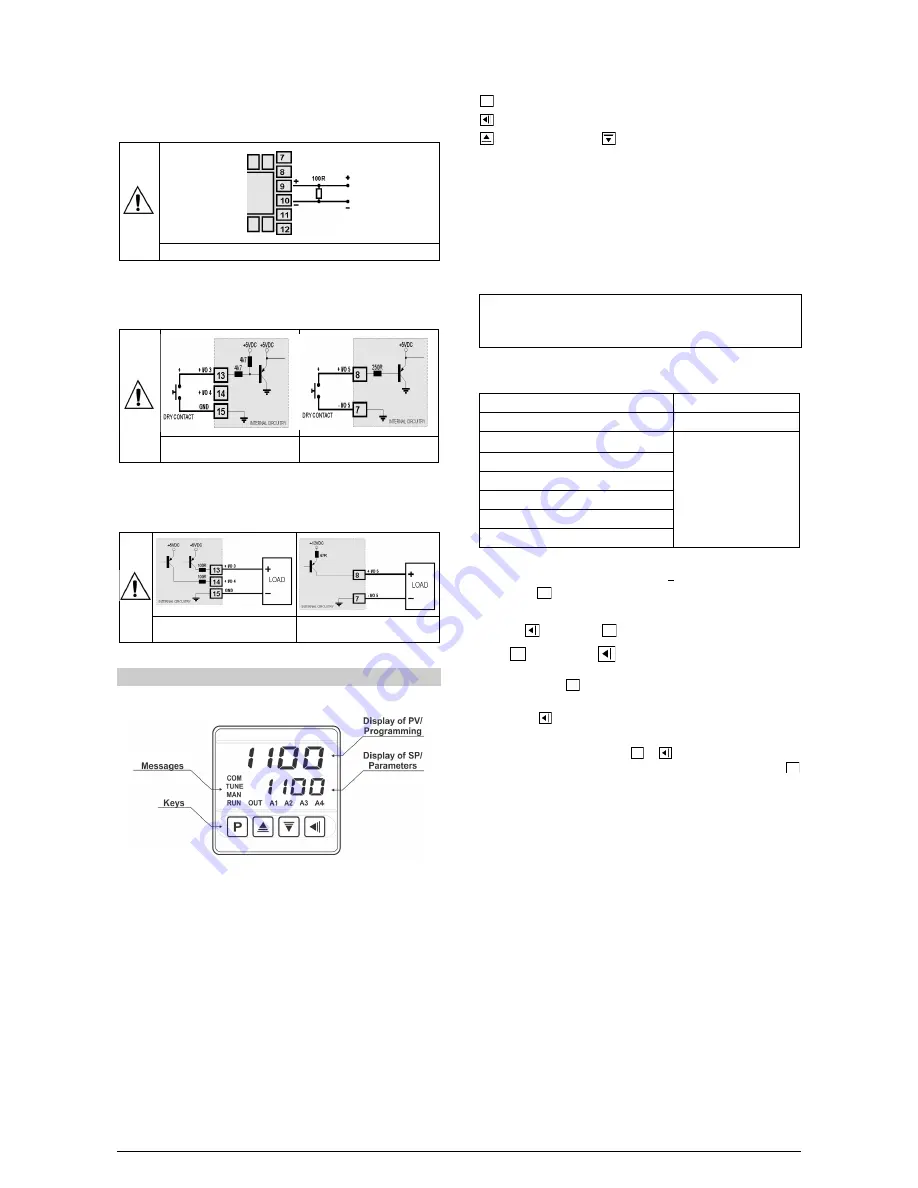
The controller's front panel, with its parts, can be seen in the Figure 7


Figure 7 - Identification of the parts referring to the front panel 

Display of  PV/Programming:  Displays the current value of PV 

(Process Variable). When in configuration mode, it shows the 

parameters names. 
Display of  SP/Parameters:  Displays the value of SP (Setpoint). 

When in configuration mode, it shows the parameters values. 
COM  indicator:  Flashes to indicate communication activity in the 

RS485 interface. 
TUNE indicator: Stays on while the controller is in tuning process. 
MAN indicator: Signals that the controller is in the manual control 

mode. 
RUN indicator: Indicates that the controller is active, with the control 

output and alarms enabled. 
OUT indicator: For relay or pulse control output; it reflects the actual 

state of the output. If an analog output is assigned for control (0-20 

mA or 4-20 mA), the OUT indicator lights continuously. 

A1, A2, A3 and  A4  indicators:  signalize the occurrence of alarm 

situation. 


  P Key used to walk through the menu parameters.  


  Back Key: used to retrocede parameters. 


  Increment key and 


  -  Decrement key:  allow altering the 

values of the parameters. 
When the controller is powered on, its firmware version is presented 

for 3 seconds, after which the controller starts normal operation. The 

values of PV and SP are displayed and the outputs are enabled. 
In order to operate appropriately, the controller needs a configuration 

that is the definition of each one of the several parameters presented 

by the controller. The user must be aware of the importance of each 

parameter and for each one determine a valid condition or a valid 

value. 

Note: Since many parameters depend on the input type chosen, it 

is recommended that the parameter 

TYPE

 be the first one to be 

configured.   

The parameters are grouped in levels according to their functionality 

and operation easiness. The 7 levels of parameters are: 

LEVEL 

ACCESS 

1- Operation 

Free access 

2- 

Tuning


Reserved access 

3- Programs 
4- Alarm 
5- Scale 
6- I/Os 
7- Calibration 

Tabele5 – Cycles of Parameters 

The parameters in the operation level (1

st

 level) are easily accessed 

through the 


 key. The access deeper levels use the combination 

of Keys: 


 (BACK) and 


 (PROG) pressed simultaneously 

Press 

 to advance or 

 to retrocede parameters within a level. 

At the end of each level, the controller returns to the operation level. 

Keep pressing the 


 key to move fast forward in the level. 

Alternatively, the controller returns to the operation level after 

pressing the   key for 3 seconds. 
All configuration parameters are stored in protected memory. The 

values are saved when the keys   or   are pressed after changing 

a parameter value. The value of SP is saved upon pressing the   

key or every 25 seconds.  


Содержание N1100

Страница 1: ...ts all available in the standard model Self tuning of PID parameters Automatic Manual function with bumpless transfer Four modes of independents alarms with functions of minimum maximum differential deviation open sensor and event Timer functions that can be associated to the alarms Retransmission of PV or SP in 0 20 mA or 4 20 mA Input for remote setpoint Digital input with 5 functions Programmab...

Страница 2: ...on of the program Note Even when the execution of the program is interrupted the control output remains active and controlling the process at the point Setpoint of interruption The program will resume its normal execution starting from this same point when the digital input is closed Pr 1 Digital input with function to Execute Program 1 Defines the channel as Digital Input with the function of com...

Страница 3: ...for retransmitting the PV and SP values in 0 20 or 4 20 mA This analog output is electrically isolated from other inputs and outputs The analog output signal is scalable with the output range defined by the values programmed in the parameters SPLL and SPkL It is possible to obtain a voltage output by installing a resistor shunt 550 Ω max to the current output terminals terminals 7 and 8 The actual...

Страница 4: ...e USB in any other type of connection is possible but requires a careful analysis by the person responsible for installing it When MONITORING for long periods of time and with connected inputs and outputs we recommend using the RS485 interface which is available or optional in most of our products INSTALLATION CONNECTIONS The controller must be fastened on a panel following the sequence of steps d...

Страница 5: ...hts continuously A1 A2 A3 and A4 indicators signalize the occurrence of alarm situation P P Key used to walk through the menu parameters Back Key used to retrocede parameters Increment key and Decrement key allow altering the values of the parameters When the controller is powered on its firmware version is presented for 3 seconds after which the controller starts normal operation The values of PV...

Страница 6: ...as Bias function Allows adding a percentage value between 100 and 100 to the MV control output The value 0 zero disables the function ovll Output Low Limit Lower limit for the control output Minimum percentage value assumed by the control output when in automatic mode and in PID Typically configured with 0 0 ovkl Output High Limit Upper limit for the control output Maximum percentage for the contr...

Страница 7: ...es the signal type for the remote SP 0 20 current of 0 20 mA 4 20 current of 4 20 mA 0 5 voltage of 0 5 V 0 10 voltage of 0 10 V Parameter displayed when remote SP is enabled rsll Remote SP Low Limit REMOTE SETPOINT LOW LIMIT used in conjunction with the rSxL scales the remote SP input defining the initial value in the remote SP indication range Parameter displayed when remote SP is enabled rskl R...

Страница 8: ...FIGURATION The controller provides means for protecting the parameters configurations not allowing modifications to the parameters values avoiding tampering or improper manipulation The parameter Protection PROt in the Calibration level determines the protection strategy limiting the access to particular levels as shown by the table below Protection Level Protected Cycles 1 Only the Calibration le...

Страница 9: ...t point SP0 in order to start the program execution Otherwise it will start promptly 2 Should any power failure occur the controller resumes the program execution at the beginning of the segment where it was interrupted DETERMINATION OF PID PARAMETERS During the automatic tuning the process is controlled in ON OFF mode in the programmed SP Depending on the process behavior oscillations may occur a...

Страница 10: ...urrent output Read the current indicated on the current meter and adjust the parameter ovLC to indicate this current value use the and keys Select the screen ovxC Press the and keys for the controller to recognize the calibration process of the current output Read the current indicated on the current meter and adjust the parameter ovxC to indicate this current value Press the key in order to confi...

Страница 11: ... s back panel ELECTROMAGNETIC COMPATIBILITY EN 61326 1 1997 and EN 61326 1 A1 1998 SAFETY EN61010 1 1993 and EN61010 1 A2 1995 USB INTERFACE 2 0 CDC class virtual communications port MODBUS RTU protocol SPECIFIC CONNECTIONS FOR TYPE FORK TERMINALS OF 6 3 mm FRONT PANEL IP65 polycarbonate UL94 V 2 CASE IP20 ABS PC UL94 V 0 PROGRAMMABLE CYCLE OF PWM 0 5 up to 100 seconds STARTS UP OPERATION after 3 ...

Отзывы: