


2 – Hardware Configuration
GPStation™ User Manual
9
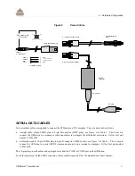
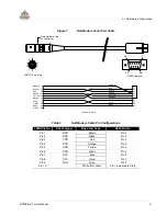
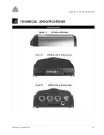
Figure 7
Null Modem Serial Port Cable
1
2
3
4
5
6
7
8
9
10
S1
S5
S6
S9
DE9S (female)
LEMO 10 pin plug
BROWN
BLACK
RED
ORANGE
YELLOW
GREEN
BLUE
VIOLET
GRAY
1
2
3
4
5
6
7
8
9
10
BROWN
RED
BLACK
GREEN
YELLOW
ORANGE
VIOLET
BLUE
GRAY
2
3
4
5
7
8
9
6
1
Red marker at top
of connector
WHITE
10-conductor cable
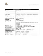
Table 3
Null Modem Cable Pin Configurations
LEMO Pin No.
RS232 Signal
Wire Color Code
DE9S Pin No.
Pin 1
DCD
Brown
Pin 4
Pin 2
RXD
Black
Pin 3
Pin 3
TXD
Red
Pin 2
Pin 4
DTR
Orange
Pin 6
Pin 5
GND
Yellow
Pin 5
Pin 6
DSR
Green
Pin 4
Pin 7
RTS
Blue
Pin 8
Pin 8
CTS
Violet
Pin 7
Pin 9
NULL
Gray
Pin 9
Pin 10
White (Not used)
Pin 1 jumpered to Pin 6
Содержание GPStation
Страница 1: ...Software Rev 3 34 OM 20000014 Rev 1 0 GPStation Products NovAtel Inc GPStation TM User Manual...
Страница 33: ......
Страница 36: ...28 GPStation User Manual NOTES...
Страница 37: ...GPStation User Manual 29 NOTES...