Setup Considerations
Chapter 3
WAAS GUS Signal Generator User Guide Rev 1
23
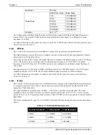
The IF output has the phase noise characteristic shown in
Table 3: IF Output Phase Noise
The L1 CW Only switch forces the unit to remove all modulation from the signal carrier (I and Q signals both
forced to zero).
Disabling of the L1 output signal from the Signal Generator occurs under specific operating conditions identified in
Section 5.2, Error Handling on Page 44
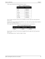
The L5 signal is filtered with a 22 MHz IF filter having the characteristics described in
.
Table 4: L5 IF Bandwidth Requirements
The L5 CW Only switch forces the unit to remove all modulation from the signal carrier (I and Q signals both
forced to zero).
The output impedance for the L1 and L5 IF Output is 50 Ohms.
Offset from Carrier
Phase Noise (<)
1 Hz
-65 dBc/Hz
10 Hz
-85 dBc/Hz
100 Hz
-90 dBc/Hz
1 KHz
-95 dBc/Hz
10 KHz
-100 dBc/Hz
100 KHz
-108 dBc/Hz
Nominal Bandwidth
3 dB Bandwidth
40 dB Bandwidth
22 MHz
> 22 MHz
< 28 MHz


