22
WAAS GUS Signal Generator User Guide Rev 1
Chapter 3
Setup Considerations
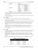
The 10 MHz output is buffered from the current system reference signal which may be the Signal Generator’s
internal OCXO or an external 10 MHz input. Its output amplitude is in the range 0 to +6 dBm and its output
impedance is 50 ohms.
For further information on the signals or connector type for the 10 MHz In and 10 MHz Out ports, please see
on
Page 52.
3.2.8
RF Out
The L1 and L5 RF Out connectors provide Radio Frequency (RF) signals from the Signal Generator.
The Signal Generator contains RF circuits to modulate and convert the digital In-Phase and Quadrature (I and Q)
data streams to an RF signal spectrum.
The nominal level of the RF Output of the Signal Generator is -50 dBm. The default frequency of the L1 RF Output
is 1227.6 MHz and can be user configured for an alternate output frequency of 1575.42 MHz. The default
frequency of the L5 RF Output is 1176.45 MHz and can be user configured for an alternate output frequency of
1227.6 MHz.
The Signal Generator L1 RF output is BPSK or QPSK modulated at a 1.023 MHz chip rate. The L5 RF output
modulation chip rate is 10.23 MHz. The RF output modulator phase on accuracy is within
±
3 degrees.
For further information on the signals or connector type for the RF Out connectors, please see
on
3.2.9
IF Out
The L1 and L5 IF Out connectors provide a 70 MHz Intermediate Frequency (IF) signals from the Signal Generator.
It is normally used to provide L1 and L5 signals that are unconverted and uplinked to the GEO satellite at the
appropriate C band frequencies.
The signal amplitude is within the range -20 dBm ± 1.0 dB for any specified I/Q configuration. The signal
amplitude is stable to within 0.25 dB over an ambient operating temperature of 15°C to 25°C. After a warmup
period of 1 hour, the L1 IF signal amplitude is stable to within 0.25 dB over a 24 hour period at a constant ambient
temperature.
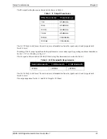
The factory configurable L1 signal (2, 4 or 22 MHz) is filtered by IF filters having the characteristics described in
Table 2: L1 IF Bandwidth Requirements
Impedance
50 ohms
Phase Noise
Offset from Carrier Phase Noise
1 Hz
<-100 dBc/Hz
10 Hz
<-130 dBc/Hz
100 Hz
<-145 dBc/Hz
1000 Hz
<-150 dBc/Hz
10,000 Hz
<-154 dBc/Hz
100,000Hz
<-154 dBc/Hz
Accuracy
±5 x 10
-13
Nominal Bandwidth
3 dB Bandwidth
40 dB Bandwidth
2 MHz
> 1.9 MHz
< 4.25 MHz
4 MHz
> 4 MHz
< 11.2 MHz
22 MHz
> 22 MHz
< 28 MHz


